


Three Phase Frequency Inverter
- Ref Price:
-

- Loading Port:
- China Main Port
- Payment Terms:
- TT or LC
- Min Order Qty:
- 1 pc pc
- Supply Capability:
- 5000pcs per month pc/month
OKorder Service Pledge
OKorder Financial Service
You Might Also Like
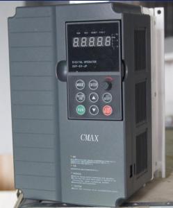
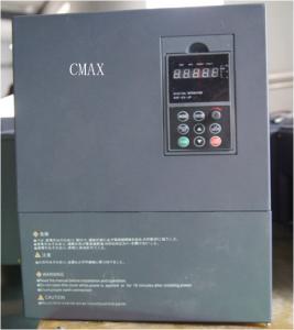
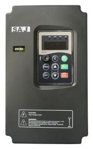
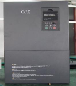
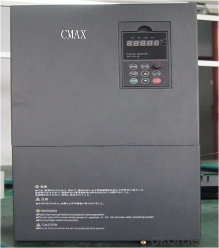
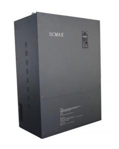
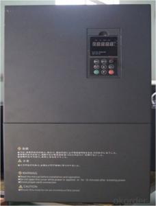
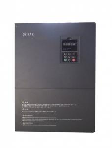
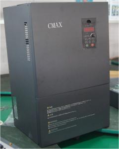
Description of Three Phase Frequency Inverter
CMAX frequency inverter is a high-quality, multi-function, low-noise variable frequency drive which is designed, developed and manufactured according to international standards. It can meet different needs of industrial conditions.The inverter applies advanced control technology of space voltage vector PWM, with functions of constant voltage control, power-off restart, dead zone compensation, automatic torque compensation, online modification parameter, high-speed impulse input, simple PLC and traverse
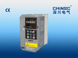
Features of Three Phase Frequency Inverter
1).Adopts 16 bit microprocessor, sine wave PWM control
2).Automatic torque ascension and automatic sliding compensation function
3).Output frequency 0.1-400 Hz
4).8 period of speed setting and 7 period can be running the program
5).Low noise, carrier frequency can from 1 kHz-15 kHz adjustment
6).Two paragraphs Acceleration and deceleration time and two segments of the S Curve slow and deceleration
7).Simulation frequency set acceptable 0-10 VDC, 4-20 mA
8).The built-in serial communication interface RS-485(baud rate can reach 38400)
9).Save energy running and automatic voltage stabilizing section function (AVR)
10).Adjustable V/F curve Acceleration and automatic and deceleration function
11).Simple vector control and built-in PID control, and the simple positioning function
12).Sleep/wake up function and zero velocity keep function
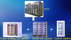
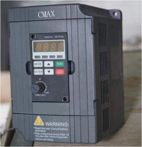
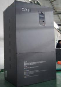
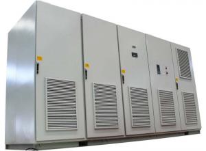
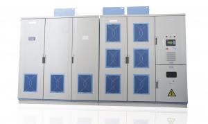
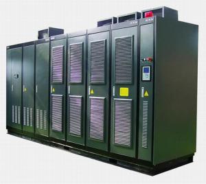
Structure of Three Phase Frequency Inverter

Application of Three Phase Frequency Inverter
★Textile: coarse spinner, spinning frame, wrap-knitting machine, loom, knitting machine, silk-spinning machine, etc.
★Plastic: extruder, hauling machine, decorating machine, etc.
★Pharmacy: mixer, roaster, etc.
★Woodworking: engraving machine, sander, veneer peeling lathe, etc.
★Papermaking: single type papermaking machine, etc.
★Machine tool: non-core grinding machine, optical lens grinding machine, cutting mill, etc.
★Printing: cloth-washing machine, dye vat, etc.
★Cement: feeder, air blower, rotary furnace, mixer, crusher, etc
★Fan and pump: kinds of fans, blowers and pumps

Performance of Three Phase Frequency Inverter
| Item | Specification | |||||||
| Input | Rated voltage | T4 series: Three phase 380v, ±15% | ||||||
| Frequency | S/T2 series: Three/single phase 220V, ±15% | |||||||
| 50/60Hz ±5% | ||||||||
| Output | Voltage | T4 series: Three phase 0-380V | ||||||
| Frequency | S/T2 series: Three phase 0~220v | |||||||
| 0-400Hz | ||||||||
| Overload ability | 150% rated current for 30s; 180% rated current for 1s; | |||||||
| Dissipation | Cooling type | Forced Cooling | ||||||
| Temperature protection | Heatsink temperature >85℃ trip protection against overheat | |||||||
| Fan control | Heatsink temperature> 50℃, fan forced operation, frequency inverter continue work | |||||||
| Control | Control mode | Open-loop vector control, V/F control | ||||||
| Performance | Start torque | Open-loop vector control: 0.5Hz 180%; | ||||||
| VF control: 0.5Hz 150% | ||||||||
| Speed range | Open-loop vector control:1:150; | |||||||
| VF control:1:100 | ||||||||
| Speed control precision | Open-loop vector control: ±0.2%; | |||||||
| VF control:±0.5% | ||||||||
| Function | Channel of operation command | Keyboard control,terminal control,communication control | ||||||
| Start mode | Direct start, DC injection braking before start, speed tracking before start | |||||||
| DC injection braking | Start DC injection braking, stop DC injection braking | |||||||
| Dynamic braking | Built-in braking unit | |||||||
| Frequency source choice | Keyboard digital frequency setting, analog AVI setting | |||||||
| PID control setting, telecommunications setting | ||||||||
| Frequency resolution | Keypad setting:0.01Hz; Analog setting: 0.1% | |||||||
| Carrier frequency | 1Khz~12Khz, | |||||||
| Acc/Dec time | 0.1~6000.0s or 0.01~600.00s | |||||||
| Signal | Analog input | AVI:0~10V | ||||||
| ACI:4~20mA | ||||||||
| Keyboard potentiometer input: 0~10V | ||||||||
| Analog output | AFM:0~10V or 0~20mA, Select through JP1 jumper | |||||||
| Digital input | A total of 28 kinds of function could be selected from S0 ~S5. | |||||||
| Digital output | 1 channel open collector output(MO1-MCM) | |||||||
| 1 channel relay output( TA-TC normally open, TB-TC normally closed; | ||||||||
| Communication Port | Communication protocol | Based on RS485 hardware, support standard MODBUS protocol. | ||||||
| Display Functions | Four digital tube display | Can monitor the operation state of frequency inverter flexibly and conveniently. | ||||||
| Installation | Humidity | Less than 90%RH | ||||||
| condensation | ||||||||
| Vibration | Less than0.6G | |||||||
| Elevation | 0~1000m, reduce the rated specification 10% when lift 1000m for each. | |||||||
| Storage temperature | -20~60℃ | |||||||
| Structure | Defend degree | IP20 | ||||||
- Q: The parameters of the inverter is 4, 6 motor can be used
- Inverter parameters are 4, 6 motor can be used. Parameters can be changed, the general inverter has a special number of motor parameters set, as well as the motor speed settings, if the series can not be changed, put the speed out of the necessary amplification of the inverter to enlarge some.
- Q: What is the number of parameters of the motor frequency of the Siemens inverter?
- Different types of Siemens frequency changer pole pair parameters different. 6SE70 is p109; The following is the p109 parameter description: P109 * Motor #PolePairs 109 For the synchronous / asynchronous motor input motor pole pairs of the function parameters. If the rated frequency (P107) and rated speed (P108) change, automatic calculation This parameter, if necessary, checks and verifies this parameter. note: - for some of the pulsed encoders (P130 = 11, 12, 15, 16) The maximum number of pole pairs of P109 = 15 can be achieved - P109 must be written when the write function (P060 = 6) is implemented. - Automatic calculation of the pole pair on the motor with regenerative feedback on the rated data Number to be added. Where the function map: 360.2, 361.2, 362.2, 363.2, 364.2 ? MM4 series is r313, which is calculated by the input rated frequency and rated speed calculated read-only value, must be selected in the p3900 to calculate the correct value. You can also set pole pairs by p314. ? S120; G110; G120; G130; G150; S150 with MM4 series.
- Q: What is the application of variable frequency speed control?
- Frequency conversion is to change the power supply frequency, thus regulating the load, play a lower power consumption, reduce losses, extend the service life of the role. Frequency translation. Frequency conversion technology is the core of the inverter, through the conversion of the power supply frequency to achieve the motor speed regulation of the automatic adjustment of the 50Hz fixed-line frequency to 30-130 Hz change frequency. At the same time, also make the power supply voltage to adapt to the range of 142-270V, to solve the power grid voltage instability caused by electrical work problems. By changing the AC frequency of the way to achieve the AC control technology is called frequency conversion technology.
- Q: My inverter is the era TVF8000 series, the motor is 15KW6 pole motor, has been used for 3 years.
- If the frequency converter is selected according to the motor rated current, then the motor current exceeds the rated current, the inverter will become overcurrent protection In this case, that is, when the inverter began to select the amount of time to stay the lack of the same power, inverter general type than the fan pump type current capacity of a high grade If the inverter selection is no problem, then please see whether the inverter is working temperature is too high, too high will cause the electronic components to resist the decline in current. First, check the inverter to work the ambient temperature, the second Please check the inverter fan is damaged, clean down the inverter fan channel and fan to see if there is no plug
- Q: The inverter is running independently
- . Main working circuit (1) Operation circuit: the external speed, torque and other instructions with the detection circuit current and voltage signal comparison operation, determine the inverter output voltage, frequency. (2) voltage and current detection circuit: isolation with the main circuit potential detection voltage, current and so on. (3) drive circuit: drive the main circuit device circuit. It is isolated from the control circuit to turn on and off the main circuit device. (4) speed detection circuit: mounted on the asynchronous motor shaft speed detector (tg, plg, etc.) signal for the speed signal into the operation loop, according to the command and operation can make the motor running at the command speed. (5) protection circuit: the detection of the main circuit voltage, current, etc., when the overload or over-voltage and other abnormalities, in order to prevent the inverter and asynchronous motor damage
- Q: Can the inverter be used to control the speed of the DC motor?
- For the brush commutation DC motor, the speed of the output torque in a certain circumstances and the input voltage related. For this type of motor, use the inverter to control the output of the rectifier device that supplies power to the motor, which can control the speed. For the brushless DC motor, the controller is in accordance with a certain law to change the form of stator winding power supply to produce a rotating magnetic field to drive the rotor rotation. That is, the DC motor controller outside the part of the AC motor and the structure and the principle has not much difference (see below. For such motors, with the inverter to replace the controller, and control the same as the AC motor Control the speed.
- Q: Short-term short-circuit converter DC link positive and negative will damage the inverter?
- This short circuit may not necessarily line, the inverter fan has three, one is no speed line, two are pulse, three are switching signal (this is very little, I only encountered several),
- Q: Three motors, if coupled with the governor speed, is it necessary to add the inverter?
- ?Second, the variable speed: change the way the stator winding wiring to change the cage motor stator pole pairs to speed.
- Q: The emitter E of the inverter inverter module and the AC output U are not directly connected together
- Corresponding to a phase of the branch of the IGBT inverter module generally appear in pairs
- Q: First reduce the frequency of about one-third of the test, not the case, then appropriate adjustments!
- And the inverter is connected to the positive and negative bk-dk electrical Han Han device,
1. Manufacturer Overview
| Location | Liaoning,China |
| Year Established | 2001 |
| Annual Output Value | US$5 Million - US$10 Million |
| Main Markets | North America South America Eastern Europe Southeast Asia Africa Oceania Mid East Eastern Asia Western Europe |
| Company Certifications | ISO9001 |
2. Manufacturer Certificates
| a) Certification Name | |
| Range | |
| Reference | |
| Validity Period |
3. Manufacturer Capability
| a) Trade Capacity | |
| Nearest Port | DALIAN |
| Export Percentage | |
| No.of Employees in Trade Department | |
| Language Spoken: | ENGLISH,CHINESE |
| b) Factory Information | |
| Factory Size: | 5,000-10,000 square meters |
| No. of Production Lines | Above 10 |
| Contract Manufacturing | OEM Service Offered Design Service Offered Buyer Label Offered |
| Product Price Range | Low and/or Average |
Send your message to us
Three Phase Frequency Inverter
- Ref Price:
-
- Loading Port:
- China Main Port
- Payment Terms:
- TT or LC
- Min Order Qty:
- 1 pc pc
- Supply Capability:
- 5000pcs per month pc/month
OKorder Service Pledge
OKorder Financial Service
Similar products

Hot products
Hot Searches
Related keywords

