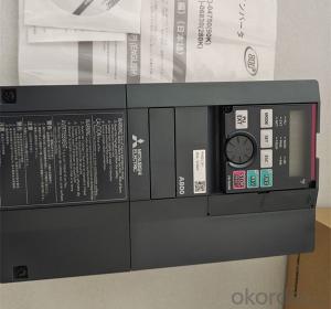


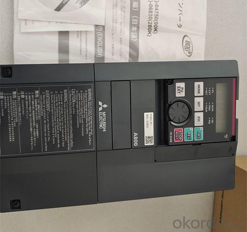


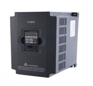
Insulating Material Intelligen Inverter FR-A820-2.2K-1
- Ref Price:
-

- Loading Port:
- Hong Kong
- Payment Terms:
- TT OR LC
- Min Order Qty:
- 1 kg
- Supply Capability:
- 2000 kg/month
OKorder Service Pledge
OKorder Financial Service
You Might Also Like


Specification
Note:
In order to prevent electric shock, the motor and frequency converter must be
grounded before use.
• Do not install the incoming capacitor or surge suppressor, radio noise filter
to the output of the frequency converter. This will lead to the failure of the
frequency converter or the damage of the capacitor and surge suppressor. If any
of the above equipment has been installed, please remove it immediately. When
it is necessary to set a non fuse circuit breaker at the output end, please
consult the manufacturer for the selection of non fuse circuit breaker.
• With regard to electromagnetic wave interference, the input / output (main
circuit) of the frequency converter contains high-frequency components, which
may interfere with the communication equipment near the frequency converter
(such as AM radio). Therefore, EMC filters are installed to minimize
interference.
• For details of peripheral devices, please refer to the user manual of each
option and peripheral device.
• PM motor cannot operate on power frequency power supply.
• Because PM motor is a motor with built-in permanent magnet, even when the
power supply of frequency converter is disconnected, as long as the motor is
still rotating, high voltage will be generated at the motor terminal. When the
output switch is closed, turn on the power supply of the frequency converter
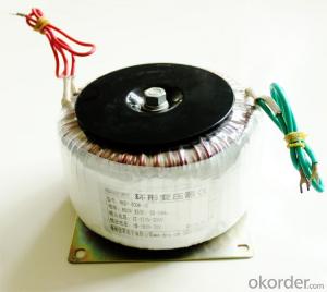
- Q: High school physics, according to the transformer U1 / U2 = N1 / N2 Can make a large voltage into a small voltage, but the small voltage can become a large voltage? Need no conditions? Can the transformer be used only for alternating current? I am now only high school physical level, answer not too esoteric or too professional! Thank you !!
- Transformers, by name, can change the voltage. Change is certainly not directional, and if you can put the voltage higher, then you can also make the voltage smaller. As long as the input and output side of the exchange, you can make the voltage larger or smaller. But some of the voltage is specified, only buck or boost. Because it has a one-way circuit. transformer:
- Q: For a project, I need a sine wave with an RMS amplitude of 1000 V at least.I have a function generator that only makes sine waves at most of 7 V RMS.I have a neon transformer w/ a 120 V primary and a 3,300 V secondary and a step down transformer w/ a 120 V primary and 16 V secondary, which is used backwards.Well, I can only get 585 V max. I decided to get some low power step down transformers (Hammond Mfg. 162 series) w/ dual primary and secondary windings. so I can try different combination of step up.I thought the smaller the core would be less of a load for the generator. I get 30 V out of the HVAC tran. (10 VA rating) when the big transformer is hooked up, but for a Hammond w/ a similar winding ratio and (1.1 VA) w/ a similar winding ratio, but I can only get like very little out of the big transformer when hooked up.Is there another factor. I read something about transformer impedance, I was thinking of doing a quick measurement of that on them.
- You are confusing VA (power ratings) with transformer ratios 120/16 7.5 :1 3300/120 27.5 : 1 So connect 7Vrms to 16 input to give output 1 52.5V Now connect this 120 (52.5V) output to the 120V input of the 120/3300 transformer The output should be approx 52.5 x 27.5 1444 Volts Use the 16/120 to step up and then the 120/3300 to step up again Take the function generator voltage to its lowest and measure at all points now gradually increase the generator voltage measuring at all points until you get what you want If the voltages are not as you expect then the VA ratings may be a problem Remember to be extra careful with High Voltages
- Q: What is the principle of the conversion of the transformer? How to restore the secondary side to the primary side?
- 3. The sum of the current: I2 '= I2 / k 4. The sum of the impedance: r2 '= k ^ 2 * r2 x2' = k ^ 2 * x2
- Q: Before engaging any technician i want to gather some knowledge about planer transformer. It will be good if u have any suggestions.
- In the planar transformers, the winding is done on flat conductive guide line of printed-circuit board printed circuit board or directly the copper mooring. Flat geometry reduce loss of skin effect when switching frequency is high, that is the eddy current loss. Therefore, effectively use the surface conductivity of copper conductor, much higher efficiency than conventional transformers. A profile map of flat transformer, and make use of the different distance between two windings, to obtained leakage inductance and impedance values under the different gap 5vdc 1a adapter.
- Q: I I am looking to buy a 208 to 480 transformer, would I simply buy a 480 to 208 and reverse the input and outputs? it's a 3 phase system and it is being supplied by an 80kW generator, then straight to an ATS to switch power from normal to emergency.
- Yes that would work.Just remember that the output current would be lower.
- Q: Hi, I replaced two 12V 20W halogen bulbs (wired in parallel) by two 3W 12V LEDs also in parallel. The problem is that the transformer (in a kitchen fume hood) seems to shut down when both LEDs are connect. It can take one but the two cause problems. I guess this might be caused by the very low resistances of the the 2 LEDs connected in parallel that short circuit the transformer? How can I reduce this short circuit without causing significant voltage drop for the LEDs? I tried using them in series but they won't work because they will then each have half the required voltage. Of course the idea is o find a solution that will also not significantly interfere with the energy savings associated with the change of halogen by LED. Btw, the LEDs are MR16 and have their own little voltage regulator/stabilizer circuit (or whatever that is).Thanks!
- 12v Halogen Transformer
- Q: Transformer Wiring and Principle
- In the three-phase transformer, each core is wound around the original winding and the secondary winding, the equivalent of a single-phase transformer. Three-phase transformer high-voltage winding commonly used A, B, C, the end with X, Y, Z to represent . The low-voltage windings are represented by a, b, c and x, y, z. The high and low voltage windings can be connected in star or triangular lines, respectively. In low-voltage winding output for low voltage, high current three-phase transformer (such as plating Transformers), in order to reduce the low-voltage winding wire area, low-voltage winding also has six-phase star or six-star star connection. China's production of power distribution transformers are used Y / Y0-12 or Y / triangle -11 two standard wiring method. The number of 12 and 11, said the original winding and secondary winding line voltage difference, that is, the so-called transformer wiring group do not.
- Q: assuming a delta connected single phase transformers , why is the neutral side is connected to ground, my question is will the current be shunted to ground since it has a low resistance??? please explain
- In electric distribution structures transformers are available countless sizes. Heavy ones are generally located on the floor with a concrete pad located under it to furnish help. those pad fastened transformers are risk-free against touch with the regularly occurring public generally with a fence. Pole fastened transformers are lighter and can be accurately located immediately on the skill pole. i don't comprehend of any floor fastened transformers different than for transformers located in vaults while the distribution strains are underground. yet those additionally desire some form of pad under them.
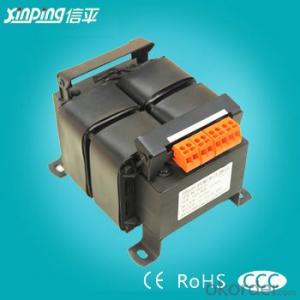
- Q: Transformer is the transmission of electrical equipment
- Transformer (Transformer) is the use of electromagnetic induction principle to change the AC voltage of the device, the main components are primary coil, secondary coil and core (core). The main functions are: voltage conversion, current conversion, impedance conversion, isolation, voltage regulator (magnetic saturation transformer) and so on. According to the purpose can be divided into: power transformers and special transformers (electric furnace change, rectifier, frequency test transformer, voltage regulator, mine transformer, audio transformers, IF transformers, high-frequency transformers, impact transformers, instrument transformers, electronic transformers , Reactors, transformers, etc.). Circuit symbols commonly used as the beginning of the number. Example: T01, T201 and so on. Transformer consists of iron core (or core) and coil, the coil has two or more than the winding, which connected to the power supply winding called the primary coil, the rest of the winding called secondary coil. It can transform AC voltage, current and impedance. The simplest core transformer consists of a soft magnetic material made of iron core and set on the core of the two turns ranging from the composition of the coil,
- Q: I want to make presentation about transformers, I need to know suitable definition.I also want to know the Major Components, and Protection devices.Thanks a lot
- Watch Popular Movies Online
Send your message to us
Insulating Material Intelligen Inverter FR-A820-2.2K-1
- Ref Price:
-
- Loading Port:
- Hong Kong
- Payment Terms:
- TT OR LC
- Min Order Qty:
- 1 kg
- Supply Capability:
- 2000 kg/month
OKorder Service Pledge
OKorder Financial Service
Similar products
Hot products


Hot Searches

