


thermal overload protection relays JZC1-71.80 thermal relays magnetic overload relay overload relay
- Ref Price:
-

- Loading Port:
- Ningbo
- Payment Terms:
- TT OR LC
- Min Order Qty:
- 100 pc
- Supply Capability:
- 5000 pc/month
OKorder Service Pledge
OKorder Financial Service
You Might Also Like
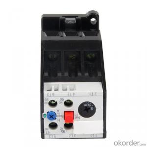

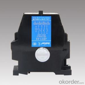
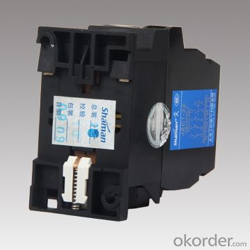
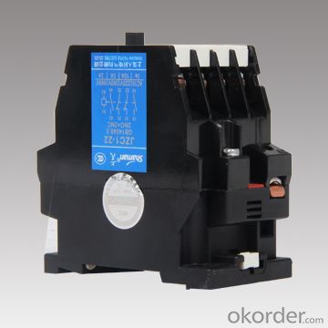
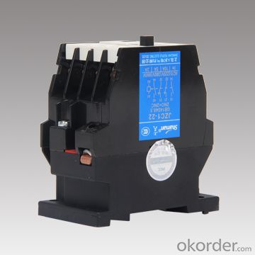
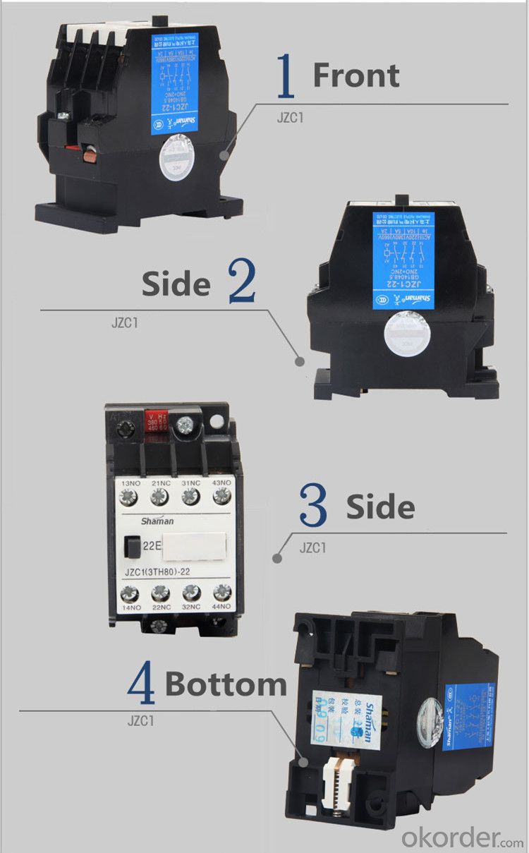
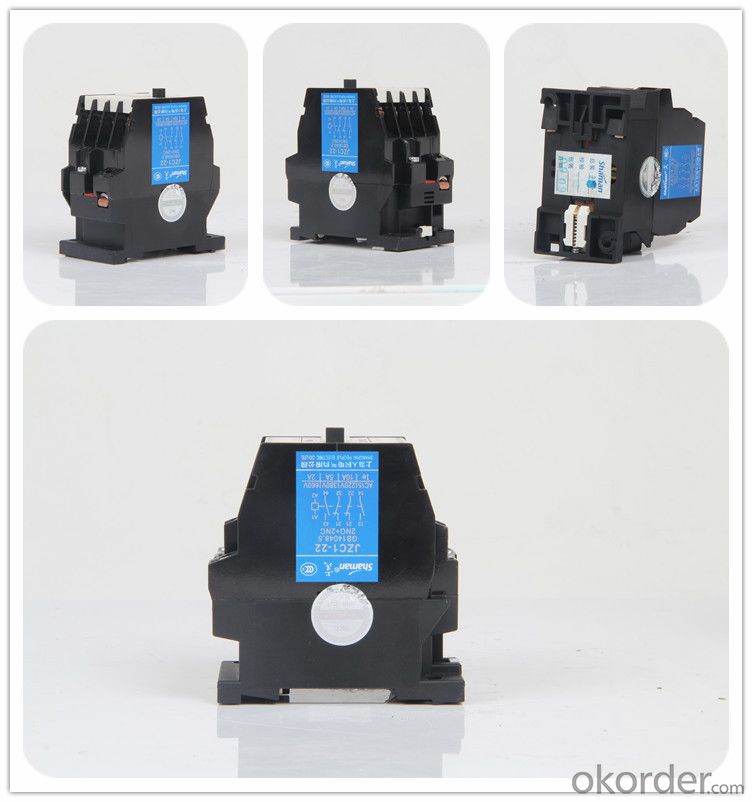
JZC1-71.80 Thermal Relay
Product Details | |||
Brand Name | Shaman | Item No. | JZC1-71.80(3TH82-71.80) |
Color | Black | MOQ | 100 pcs |
Packing | 40 PCS in one carton. | ||
Important Information | |||
Send sample | Yes | ||
Delivery time | Within 30 days. | ||
Payment terms | T/T 30% deposit, the balance before the shipment. | ||
Introduction:
JZC1 contactor type relay for AC 50Hz or 60Hz, rated voltage up to 660V or 600V DC,
rated voltage control circuit to control a variety of electromagnetic coils, so the signal is
sent simultaneously to expand or to signal to the control components.
Specifications:
The technical parameter of JZC1 series Contactor type Relay as follows:
Place of Origin: Zhejiang China(Mainland) | Brand Name: Shaman | Model Number: JZC1 |
Rated frequency: 50Hz | Rated operational voltage: Up to 660V | Rated current(Ie):AC-15: 5DC-13:0.25 |
Description | AC 50Hz, rated voltage up to 660V, rated insulating voltage up to 690V |
Control various kinds of magnetic coils, amplify the signals, electric interlocking or transmit the signals to the controlled element | |
Long-distance connecting and breaking circuit, for frequency start,stop and control small capacity ACmotor | |
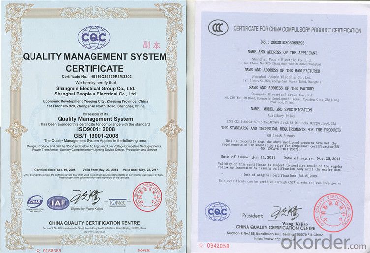
Certificate | CCC, RoHS certificates |
Standard | IEC 60947-5-1/GB14048.5 |
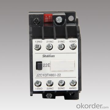
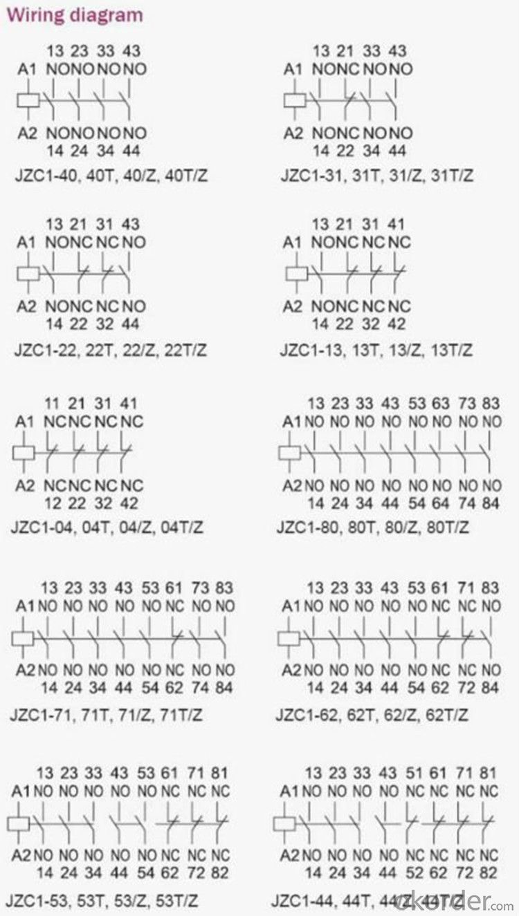
Technical data | Auxiliary contact: 4sets,8sets |
Auxiliary structure: single ply double ply Auxiliary combination: NO NC NO NC 1 3 4 4 2 2 5 3 3 1 6 2 4 0 7 1 0 4 8 0 | |
Operating frequency: 3600time/h | |
Electric life: 1*106 Mechanical life: 10*106 | |
Coil voltage: AC 12~660V DC 12~250V | |
Coil pull-in voltage:80%~110%Us Coil release voltage:20%~75%Us(AC),10%~75%Us(DC) | |
Weight(kg): 0.5(AC single ply) 0.44(AC double ply) 0.7(DC single ply) 0.69(DC double ply) | |
Features | Direct-action structure of Double breaking points |
Sealed auxiliary system structure | |
Terminal with protective covering | |
Also can Handle check | |
Fixed mode: Screw-up and 35mm TH Rail mounting |
Using sort | AC-15 | DC-13 | ||||
Rated working voltage V | 220 | 380 | 660 | 110 | 220 | 600 |
Rated working current A | 10 | 6 | 2 | 0.9 | 0.45 | 0.2 |
Working conditions:
1.The ambient air temperature:
a).The ambient air temperature is up to 40 °c Celsius.
b).The average does not exceed 35 °c Celsius within 24 hours.
2.The ambient air temperature is below to -5 °c Celsius.
3.The altitude of the installation sites do not exceed 2000m.
4.The pollution degree of installation sites is level 3.
5.Installation category is class II.
6.The tilt with the vertical is not more than 5 °c.
7.No space of significant shake and shock and vibration
Control circuit:
The standard value of the rated control power supply and voltage (Us):
AC (50Hz)36V,48V,110V,220V,380V
(60Hz)42V,58V,132V,264V,460V
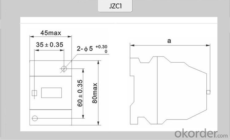
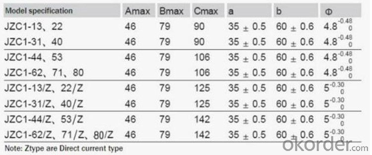
Overall and installation dimension(mm):


- Q: What are the smart relays, what are their special effects? Where is it?
- Intelligent relays are widely used in recent years, intelligent lighting switch. You can use the microcontroller to control it, when it reaches the operating voltage can turn on the circuit, or from the blocking effect, in many areas have applications. For safety, can play a long-range control role. Relay (relay) is an electrical control device, when the input (excitation amount) changes to meet the specified requirements, in the electrical output circuit to control the amount of a predetermined step changes in an electrical appliances. It has a control system (also known as the input circuit) and the control system (also known as the output circuit) between the interaction. Usually used in automated control circuits, it is actually a small current to control the operation of a large current "automatic switch". So in the circuit plays an automatic adjustment, security protection, conversion circuit and so on.
- Q: Mitsubishi Q series relay L and M difference
- I generally understand that L is a live hold of M, want to reset L, must be reset by instruction (eg RST).
- Q: With the following instrument to do the relay action test, the experimental results out of a "action time = 0.112ms", I would like to ask the Secretary to collect action time principle is what kind of?
- Specifically, use a storage recorder (Japan Japan 8860-50, etc.) and two voltage probes. One probe is connected to the input of the relay and the other is connected to the output. This recorder can see the action time to compare two signals.
- Q: Three-phase phase and phase sequence protection relay how wiring, but also what accessories? How I connected to the power after the end of no electricity
- Only the bottom of the contact control, no internal power supply, the need for external power supply, usually use the phase sequence protector to control the relay relay relay, and then through the relay relay control the total power contactor.
- Q: The power supply voltage of the relay is not the same as the control voltage
- Of course not the same, you said the power supply voltage is added to the coil voltage, generally 5V, 12V, 24V and several other, plus the power supply voltage relay to pull, after the contact contact on the contact,
- Q: Time relay What is the meaning of instantaneous action, can not use an actual circuit example shows how the next momentary and ordinary delay, the difference in that
- The general time relay has two pairs of contacts, different models of time relay, respectively, there are two pairs of normally closed, normally open delay contact or a pair of normally closed, normally open delay and instantaneous normally closed, normally open contact. Instantaneous normally closed, normally open contacts and relay contacts the same function, power is action, power is reset. Take the air damping time relay as an example to illustrate: When the coil is energized, the armature and the pallet are attracted by the core and instantaneously move down to turn on or off the instantaneous action contact. But the piston rod and lever can not fall along with the armature at the same time, because the upper end of the piston rod attached to the rubber chamber in the chamber, when the piston rod in the release of the spring under the action of downward movement, the rubber film with the concave, The air in the air chamber becomes thin and the piston rod is damped and slowly descends. After a certain period of time, the piston rod down to a certain position, then through the lever to promote the delay contact action, so that moving off the contact open, moving contact closure. From the coil power to the delay contact to complete the action, this time is the relay delay time. So in fact, for the general time relay (including electromagnetic, air damping, electric, etc.), instantaneous contact trigger action and delay contact from the trigger effect is the same, but because the trigger action speed The difference between the two action mode delay time level is not the same, but the general instantaneous type according to the different rated voltage of the model can only reach 220V, and the ordinary can reach 380V.
- Q: What are the characteristics of the special auxiliary relay M8012?
- Mitsubishi m8012 is 100ms clock That is to say you ld m8012 out y0
- Q: What is the role of intermediate relays? Used in what circuit.
- Intermediate relay is mainly used in the control circuit, its role is mainly composed of control relay disk, the control of the role of the circuit.
- Q: The difference between the contactor and the relay, the symbols in the circuit
- Contactor is the master, the equivalent of the switch, in the circuit connected or cut off the main circuit, the symbol is generally: C Relay is the auxiliary control, for the control circuit, it has a lot of types, the common symbol: J, subdivided down, there are intermediate relay: ZJ Time relay: SJ, thermal relay: RJ, and so on.
- Q: What is the meaning of the time relay?
- The general relay power will immediately close the normally closed power, disconnect the normally open break point, the delay relay is different from the power is turned on after the power will not immediately disconnect, and will wait for a set of your time And then disconnected.
Send your message to us
thermal overload protection relays JZC1-71.80 thermal relays magnetic overload relay overload relay
- Ref Price:
-
- Loading Port:
- Ningbo
- Payment Terms:
- TT OR LC
- Min Order Qty:
- 100 pc
- Supply Capability:
- 5000 pc/month
OKorder Service Pledge
OKorder Financial Service
Similar products
Hot Searches

