
JRS2 series of thermal relay electrical contactors and relays electronic overload relay
- Ref Price:
-

- Loading Port:
- Ningbo
- Payment Terms:
- TT OR LC
- Min Order Qty:
- 100 pc
- Supply Capability:
- 5000 pc/month
OKorder Service Pledge
OKorder Financial Service
You Might Also Like
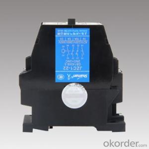


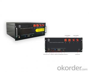
JRS2-80/Z Thermal Relay
Product Details | |||
Brand Name | Shaman | Item No. | JRS2-80/Z |
Color | Black | MOQ | 100 pcs |
Packing | 30 pcs in one carton based on the items of products. | ||
Important Information | |||
Send sample | Yes | ||
Delivery time | Within 30 days. | ||
Payment terms | T/T 30% deposit, the balance before the shipment. | ||
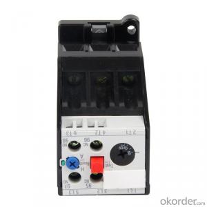
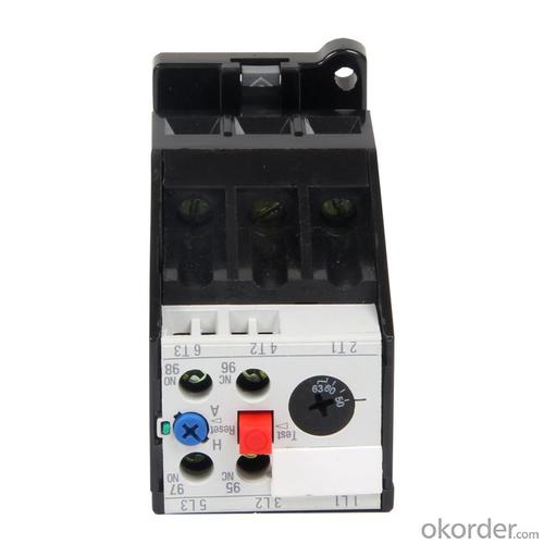
Introduction:
JRS2 thermal relay is suitable for AC 50/60Hz, voltage up to 660V and current up to 630A,general AC motor of long or discontinuous long operation, used as overload protection and has the functions of breaking phase protection, temperature compensation, and trip indication.
It can automatically and manually get back. It can be fixed with contactor CJX1 together, also be independently fixed.
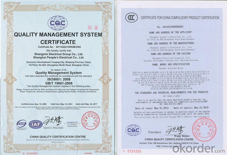
The product conforms to IEC60947-4-1 standard.
Motion Characteristic:
(Three-phase Balance Motion Time)
| No | Times of the setting current | Motion time | Start condition | Ambient temperature | ||
| 1 | 1.05 | >2h | Cold state | 20±5℃ | ||
| 2 | 1.2 | <2h< span=""> | Heat state(Following the No.1 test) | |||
| 3 | 1.5 | <4min< span=""> | ||||
| 4 | 7.2 | 10A | 2s< Tp≤10s | ≤63A | Cold state | |
| 10 | 4s< Tp≤10s | >63A | ||||
Phase-losing Motion Characteristic:
| No | Times of the setting current | Motion time | Start condition | Ambienttemperature | |
| Any two phases | Another phase | ||||
| 1 | 1 | 0.9 | >2h | Cold state | 20±5℃ |
| 2 | 1.15 | 0 | <2h< span=""> | Heat state(Following the No.1 test) | |
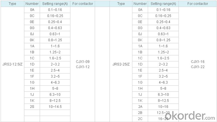
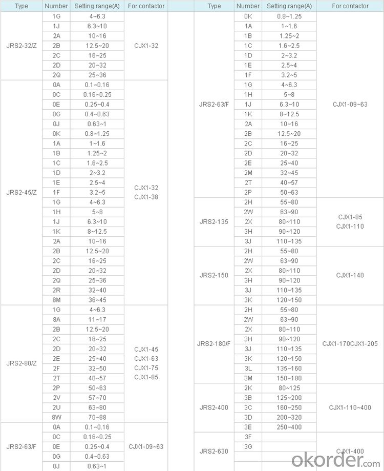
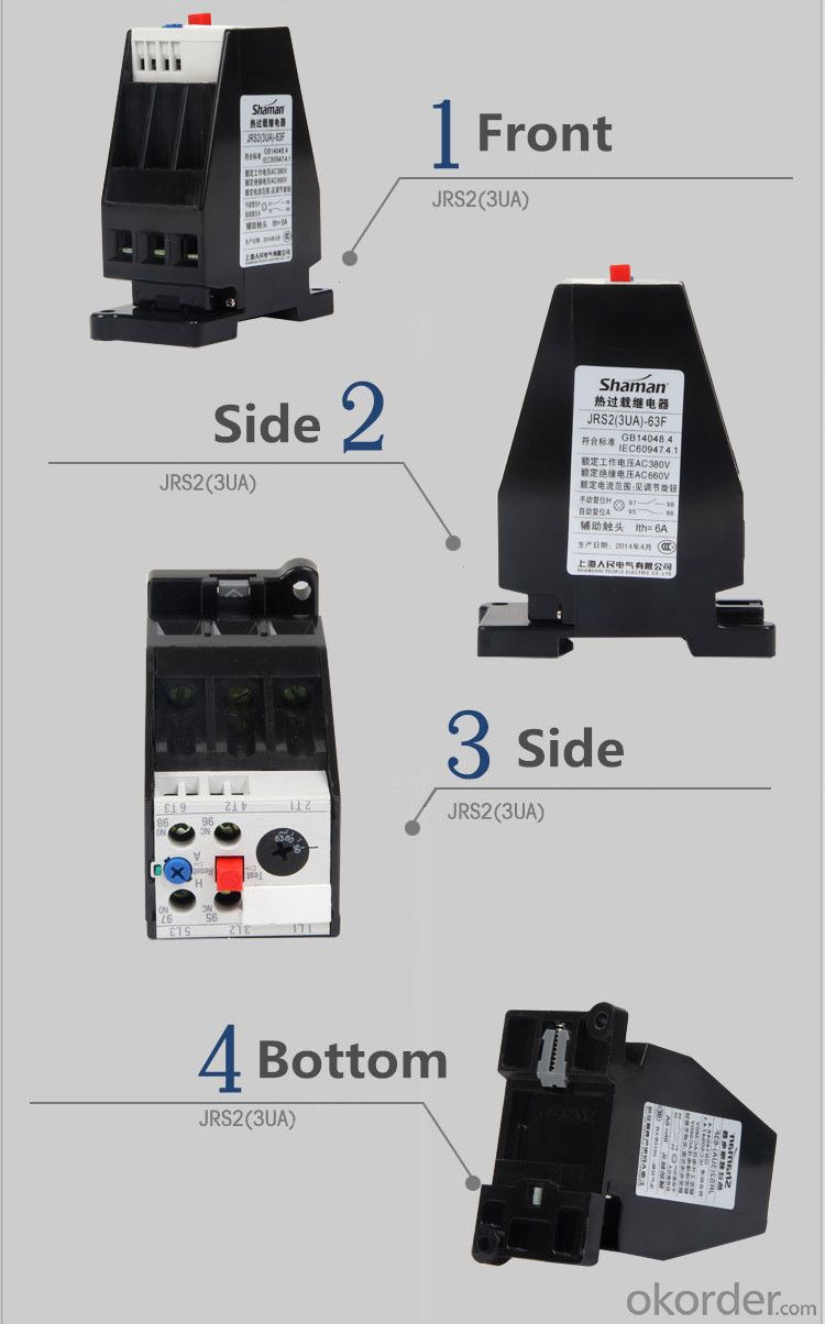
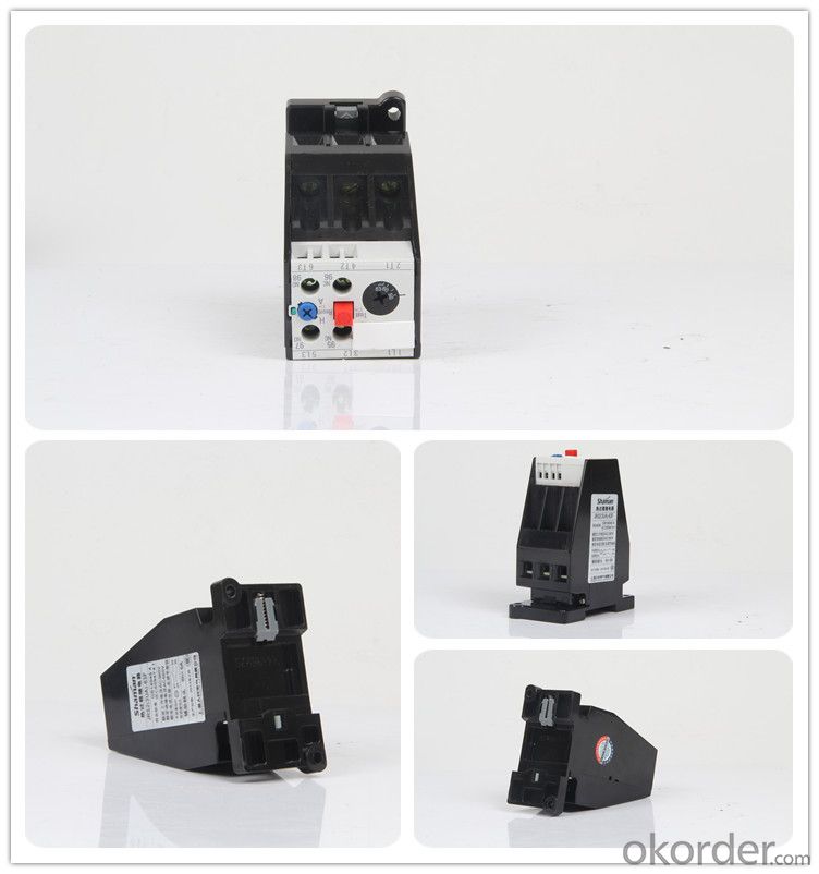
Specification:
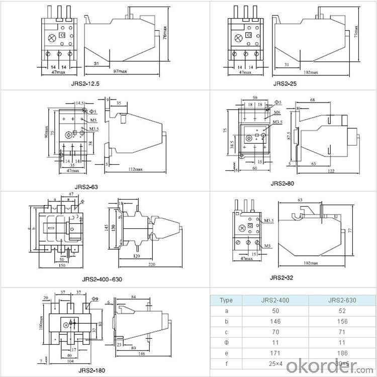
Outline and Mounting Dimension:
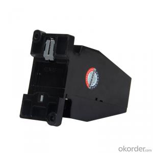
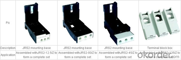
Accessories:


Why Chose us:
We have our own engineer teams,will supply the professioanl design for you.
Every new product can be made accurate by your design and demand.
Enough stock to fit your urgently need.
Keep smooth delivery on time.
Perfect package according to your demand.
Our service:
7day*24hours Hot-line & Email Service.
Your inquiry related to our products or prices will be replied in 24hours.
Well-trained and experienced staffs to answer all your questions in fluent English.
OEM&ODM is available.
- Q: Briefly describe the structure of time relay
- Early in the AC circuit often used in the air damping type time relay, which is the use of air through the small hole throttling The principle to get the delay action. It consists of electromagnetic system, delay mechanism and contact three parts. Any relay that senses the component to an action signal, its actuator (contact) to delay a certain time before the action of the relay called the time relay. At present the most commonly used for large-scale integrated circuit type of time relay, it is the use of resistance to the principle of delay to achieve action. In the AC circuit is often used to step down the transformer, integrated circuit as a core device, the output using a small electromagnetic relay, making the product performance and reliability than the early air damping time relay is much better, the product timing accuracy and Control also increased a lot.
- Q: I was beginner PLC, with Delta PLC to do programming, with time relay software is not, please refer to the predecessors
- Explanation of program: When X0 = On, the present value of the timer T0 is counted at 100 ms. When the timer now value = set value K100, the output coil T0 = On. When X0 = Off or power failure, the current value of timer T0 is cleared to 0 and output coil T0 becomes Off.
- Q: Why the circuit breaker or knife lockout circuit can not use heavy relay
- The circuit breaker and the disconnector of the isolation circuit to receive the switch and the switch of the auxiliary node, then re-relay, if the maintenance of the operation when the power is off, the relay may return, the electric shock can not reflect the switch and the switch The real state may lead to misuse.
- Q: Ask you, the insulation class is the insulation grade F, the F-level on behalf of what does this mean?
- Therefore, Class B insulation indicates that the insulation temperature of the generator used is 130 ° C.
- Q: What is the speed relay working principle?
- The speed relay works as follows: The speed relay rotor shaft is connected to the axis of the controlled motor and the stator is mounted on the rotor. When the motor rotates, the speed relay rotor rotates, the stator short-circuit conductor will cut the magnetic field, resulting in induced electromotive force, resulting in current. This current generates torque with the rotating rotor magnetic field, and the stator starts to rotate. When the turn to a certain angle, mounted on the stator shaft pendulum to promote the reed action, so that normally closed contact breaking, normally open contact closed. When the motor speed is below a certain value, the torque generated by the stator is reduced and the contact is reset under the action of the spring. Commonly used speed relay with YJ1 type and JFZ0 type. Usually the speed of the relay action speed of 120r / min, reset speed of 100r / min. Turn left to turn right
- Q: That is, there are two 220 power supply all the way to the battery inverter is the way the general electricity I would like to use a large relay relay to implement automatic conversion, when the electricity is normal when the relay is used in conjunction with the electricity When the power failure when the relay is connected to the inverter on the way that I do not know it?
- To consider the size of the switching circuit load, the contact capacity to be greater than the circuit current. ???? Also if the capacity is not the case, you can not use the relay, directly with a thyristor on it. Fast response, switching without any feeling, (commonly known as: uninterruptible power supply UPS)
- Q: What is zero pressure relay?
- Under normal circumstances is achieved with SCR, the detection of AC voltage zero when the open SCR, the current zero off when the zero. This can reduce the electromagnetic interference to other devices.
- Q: What is the general certification of the relay?
- Relay certification generally have: CQC certification, CE certification, TUV certification, UL certification, FCC certification, VDE certification Wait
- Q: What is a jump relay? What is its main function?
- Jump relay By the appropriate fit of the winding and the wave winding mixed with a DC armature winding. The windings and windings of the windings are connected in parallel to the same commutator. Because of its coil shape is like a frog named after the name. This winding due to wave winding coil and winding coil between each other plays a uniform line, so no need to add another pressure line.
- Q: ABB's relay in the same model 1CO and 2CO What is the difference?
- It has a control system (also known as the input circuit) and the control system (also known as the output circuit) between the interaction. Usually used in automated control circuits, it is actually a small current to control the operation of a large current "automatic switch".
Send your message to us
JRS2 series of thermal relay electrical contactors and relays electronic overload relay
- Ref Price:
-
- Loading Port:
- Ningbo
- Payment Terms:
- TT OR LC
- Min Order Qty:
- 100 pc
- Supply Capability:
- 5000 pc/month
OKorder Service Pledge
OKorder Financial Service
Similar products
Hot Searches
Related keywords

