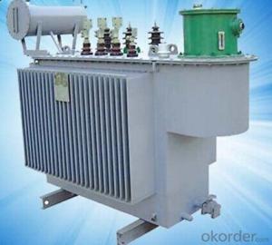
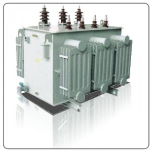
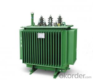
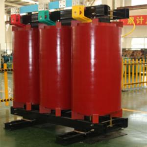
SH(B)15-M-30~2500/10KV Three Phase Amorphous Metal Alloy Distribution Transformers
- Ref Price:
-

- Loading Port:
- Shanghai
- Payment Terms:
- TT OR LC
- Min Order Qty:
- -
- Supply Capability:
- -
OKorder Service Pledge
Quality Product, Order Online Tracking, Timely Delivery
OKorder Financial Service
Credit Rating, Credit Services, Credit Purchasing
You Might Also Like


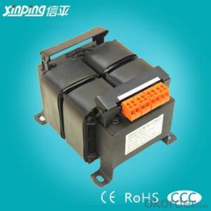
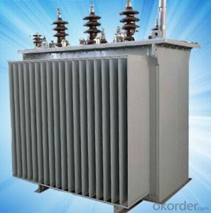
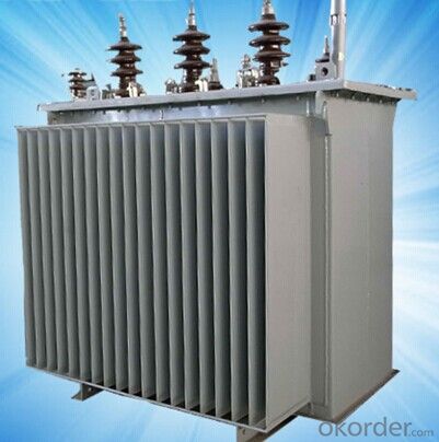
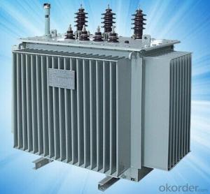
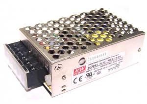
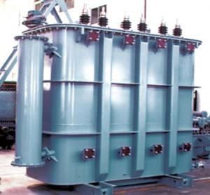
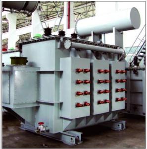
SH(B)15-M-30~2500/10KV three phase amorphous metal alloy distribution transformers is suitable for distribution system with 10KV.50HZ for industrial and mine enterprise ,power illumination.it confirms to GB1094<power transformer>standard.
its performance level reaches international advasnced level of 90s similar product,it has strongpoint of advanced woekmanship,novel design.nice appearance and less ground demand.low damage,low noise.strong anti-short circuit.
15-M-30~2500/10KV Three Phase Amorphous Metal Alloy Distribution Transformers")
- Q: Single bus sub-section for power distribution, transformer with a prepared and dual-use how to understand
- One with a prepared, you can only put one of the transformer, any of its transformers can all the load to bring all the general into the line breaker and bus in the breakdown of the circuit breaker, interlock between the three, A change vote, B variable can not vote, or vice versa, B cast A can not vote. This is the nature of the load mostly for a load, power supply is necessary for high reliability, but also the largest investment. Dual use can be divided into several, mainly refers to the change can be put into use, and some can be put into the parallel use, in some cases is not allowed to use in parallel, is the three circuit breakers with interlocking Three locks two spoons, three circuit breakers can only vote two. At the same time the capacity of the transformer is also different, some are prepared, some are dark spare, the specific use depends on how the original system design. hope this helps.
- Q: According to your measurements when we have a step-up or a step-down transformer?
- A transformer is a device that transfers electrical energy from one circuit to another through inductively coupled conductors—the transformer's coils. A varying current in the first or primary winding creates a varying magnetic flux in the transformer's core and thus a varying magnetic field through the secondary winding. This varying magnetic field induces a varying electromotive force (EMF) or voltage in the secondary winding. This effect is called mutual induction. If a load is connected to the secondary, an electric current will flow in the secondary winding and electrical energy will be transferred from the primary circuit through the transformer to the load. In an ideal transformer, the induced voltage in the secondary winding (Vs) is in proportion to the primary voltage (Vp), and is given by the ratio of the number of turns in the secondary (Ns) to the number of turns in the primary (Np) as follows:- Ns/Np Vs/Vp ---------------------(i) By appropriate selection of the ratio of turns, a transformer thus allows an alternating current (AC) voltage to be stepped up by making Ns greater than Np, or stepped down by making Ns less than Np.
- Q: I got stuck in a problem while solving the previous exam question for my courseTwo transformers with unequal turn ratio and unequal ratings are connected in parallel and have the same secondary voltage. How will the load be distributed between them? Hence find the circulating current.I know how to find the circulating current when the secondary voltages are different. But how can there be a circulating current if the secondary voltage is same?And I know about the load distribution being inversely proportional to the line impedance of the transformers, but what will be the change taking circulating current into account?
- If I understand this correctly, then you have this situation, let T1 be the first transformer and T2 the second one The input voltage is connected to the primary of T1 The secondary of T1 is connected to the primary of T2 the secondary of T2 is connected to the load If the secondaries are at the same voltage then T1 secondary voltage T1 primary voltage T2 secondary voltage. This can only happen if the turns ratio of T2 is 1:1, i.e it has the same number of turns on the primary and the secondary. Does that help?
- Q: When the transformer voltage is a rated voltage, the secondary voltage in the end is how to change with the load, what is the basis for the theory of the way you ask you about the inrush
- 2 excitation current characteristics When closing the circuit breaker to charge the transformer, sometimes you can see the transformer ammeter pointer put great, and then quickly return to the normal no-load current value, the impact current is usually called the inrush current, features are as follows: 1) The inrush current contains high-order harmonic components (mainly secondary and tertiary harmonics), so the variation of the inrush current is a steep wave. 2) The attenuation constant of the inrush current is related to the saturation of the core. The deeper the saturation, the smaller the reactance and the faster the attenuation. Therefore, at the beginning of the moment decay quickly, then gradually slow down, after 0.5 ~ 1s after its value does not exceed (0.25 ~ 0.5) In. 3) Under normal circumstances, the greater the capacity of the transformer, the longer the duration of attenuation, but the general trend is the inrush current decay rate is often slower than the short-circuit current attenuation. 4) The value of the inrush current is very large, the maximum rated current of 8 to 10 times. When setting up a circuit breaker to control a transformer, the quick break can be set according to the transformer excitation current.
- Q: How can the locations and polarity of the windings be tested on the various legs of a core when it has 2 open(circuited) three pahse windings (III and iii)?what measurements are required , assuming that the transformer is so enclosed that only the 12 winding terminals are visible?Ohmmeter , voltmeters , a single phase voltage supply are available.
- It sounds like you have a three phase transformer. In the cover plate there normally is a drawing to guide you on what you want to do. Most trans formers can have input voltages of 440 volts in to 240 ouput. but some can provide 115 volts on the output if wired correctly. Any transfomer compnay website provide wiring drawings that pretty match everyones transformers. Contact the manufacturer of the transformer for instructions.
- Q: 2500KVA transformer rated current 3608A, how much can be overloaded current?
- Ventilated good circumstances, you can temporarily overload 300A.
- Q: I am a transformer factory salesman, the company let go to the field to run business, if you go to a strange city, where the main starting from where the few places, and which units to contact? If the local sales in the transformer factory, then work well to carry out? What are the sales channels?
- 1. Power supply company tender 2. Cabinet manufacturers 3, the installation company 4, direct customers, to the planning bureau to find, in advance to know which new project 5, design institute, know some late 6. Power supply company front desk, people come to install more late
- Q: 1. If the input voltage is 100V and output voltage is 200V, which side of the transformer winding will be primary?(a) 100V side (c) winding with loss turns(b) 200V side (d) winding with more turns2. Which of the following statement about humming of transformer is true?(a) The frequency of humming tone is 100Hz(b) The frequency of humming tone is 50 Hz(c) The humming is caused by a vibration of the low voltage winding through which the high current flows(d) The humming is caused by the private force of attraction between the lamination of the core3. In a 10 KVA, 230/1000V 1-? transformer, the no load current will be around(a) 3 A(c) 10 A(b) 0.5 A (d) 0.9 A
- Each turn produces about the same voltage, and the primary is the input side. 1. The input voltage is lower than the output voltage, so the input winding (primary) must have the lower number of turns. 2. If the line frequency is 50 Hz, then a and d, since the vibration force is proportional to the magnitude of the current, but not the direction, so both half cycles produce the same force and there are two cycles of force each voltage cycle. The main vibration forces involve the magnetic attraction between the laminations and their magneto-striction (change in dimension as magnetic flux magnitude varies) 3. The load full load primary current will be roughly the power divided by the voltage or 10,000/23043 A. The no load current will be a few percent of that current, but I do not know the typical fraction for a transformer of that size. My seat-of-the-pants guess is a, about 7%. -- Regards, John Popelish
- Q: Exactly what is the storyline of the Transformers. As far back as I know, there were two brother, Unicron and Primus who fought each other because Unicron wanted to suck up Universes. But where did these two come from? Does it even say?
- I am a fan but I haven't been able to find that out myself, if you find out let me know.
- Q: What is the meaning of the transformer 'turns ratio'? what's the effect?
- The number of turns of the primary coil (that is, the number of turns around the coil) and the number of secondary turns. Turns ratio and voltage ratio is proportional. For example, 220 volts to 10 volts voltage ratio is 220: 10, turns ratio should also be 220: 10, such as the primary is 2200 laps, the secondary should be 100 laps. Multi-turn ratio is the number of turns of the secondary output and the primary correspondence. A variety of turns ratio is to allow a sensor device is used for a variety of heat treatment process. I remember answering your question? how? Do not believe? 'U1 / U2 = n1 / n2' "/" Or ":" read here as "than", the size of the ratio is that you say the size of the divisor, you put it when the division can also be seen. U1 / U2 = n1 / n2 'U1 denotes the primary voltage of the transformer, U2 denotes the secondary voltage of the transformer, n1 denotes the number of primary turns of the transformer, that is, the number of turns, n2 denotes the secondary turns of the transformer, The number of turns, n1 / n2 is the turns ratio. The meaning of this formula is: transformer primary and secondary voltage ratio = its primary and secondary turns ratio (turns ratio) I do not know you can not understand, do not understand I can do nothing
Send your message to us
SH(B)15-M-30~2500/10KV Three Phase Amorphous Metal Alloy Distribution Transformers
- Ref Price:
-
- Loading Port:
- Shanghai
- Payment Terms:
- TT OR LC
- Min Order Qty:
- -
- Supply Capability:
- -
OKorder Service Pledge
Quality Product, Order Online Tracking, Timely Delivery
OKorder Financial Service
Credit Rating, Credit Services, Credit Purchasing
Similar products

Hot products


Hot Searches
Related keywords

