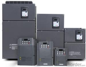
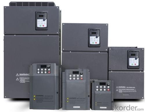
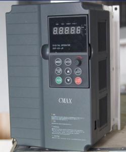
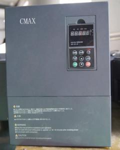
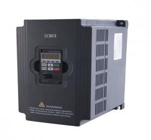
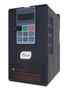
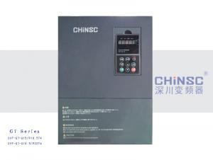
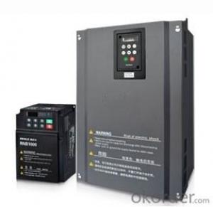
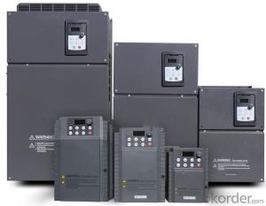
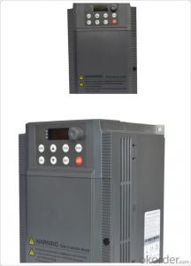
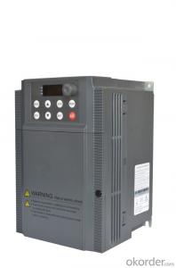
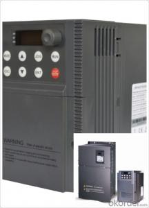
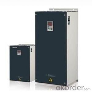
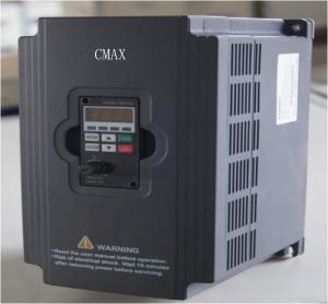
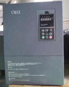
Frequency Inverter Single-phase 200V class 4KW
- Loading Port:
- China Main Port
- Payment Terms:
- TT OR LC
- Min Order Qty:
- -
- Supply Capability:
- -
OKorder Service Pledge
OKorder Financial Service
You Might Also Like
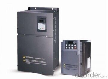
Technical specifications
Table 2.3: Technical Parameters of QD200 Series Frequency Inverters
ITEM | SPECIFICATIONS | |
Main Input | Rated voltage and frequency | Single-phase 200V class: 200V-240V,50Hz/60Hz |
3-phase 400V class: 380V-480V , 50Hz/60Hz | ||
Allowable value of change | Voltage: 380V-15% ~ 480V+10%; Frequency: ±15% | |
Main output | Output voltage | Maximum output voltage equals to input voltage |
Output frequency | 0.5 Hz to 400 Hz | |
Overload capacity | 150% of rated output current for 60s, 200% of rated output current for 2s | |
Control performance | Modulation mode | 3-phase PWM, 2-phase PWM |
Control mode | V/f control for constant torque, V/f control for quadratic load, vector control without PG (open loop control),Energy-saving | |
Setting method of run command | Outer terminal, keyboard panel or serial communication | |
Setting method of speed command | Analog setting, keyboard, serial communication, UP/DOWN speed setting from external terminal | |
Speed setting resolution | Keyboard: 0.1 Hz | |
Analog setting: 0.05/50Hz (10bit) | ||
Speed control precision | V/f control:±2% | |
vector control without PG (open loop control): ±0.2% | ||
Speed control range | V/f control 1:40 | |
vector control without PG (open loop control) 1:200 | ||
Acceleration and Deceleration Time | 0-3200.0s | |
switching frequency | 1.5 kHz ~ 12 kHz, according to junction temperature automatically reduce the switching frequency | |
Analog input | Number | 2 ways: AI1、AI2 |
Type | DC voltage or DC current | |
Maximum input range | AI1: 0 to 5VDC, 0 to 10VDC, 0/4 to 20mA DC receivable AI2: 0 to 10VDC or PTC probe input receivable | |
Analog output | Number | 1 way: AO1 |
Type | DC voltage or DC current | |
Maximum input range | Voltage output: 0 to 10V, Current output: 0/4 to 20mA | |
logic input | Number | 0.75kw-11kW:LI1,LI2,LI3,LI4,AI1,AI2 15kW-500kW:LI,LI2,LI3,LI4,LI5,LI6,LI7,LI8,AI1,AI2 note:2 virtual logic input, capable of configuring AI1 and AI2 into logic input port (positive logic or negative logic) |
Type | Source or Sink | |
Maximum input range | 0-24VDC | |
ITEM | SPECIFICATIONS | |
logic output | Number | 0.75kW-11kW: pulse signal output (LO-CLO)、relay output 1(T1A、T1B、T1C) 15kW-500kW:pulse signal output(LO-CLO)、relay output 1、2(T1A-T1B-T1C、T2A-T2B-T2C) |
pulse signal output | ||
relay output | RA-RB-RC, including a NO contact and a NC contact Maximum switch capacity: T1A,T1B: 3A at 250VAC, or 4A at 30VDC T2A,T2B: 2A at 250VAC or 30VDC | |
Serial communication interface | RS485 interface supports Modbus protocol. | |
Display | 4-digit LED digital display | For display of frequency setting, output frequency, fault code and parameter setting etc. |
Environment | Standard | Development of VSC200 series frequency inverters follows strict international standards and relevant recommended IEC and EN standards for control devices, especially IEC/EN61800-5-1 and IEC/EN61800-3. |
Altitude | Derating unnecessary when altitude is 1000m or below (Derating necessary at altitude higher than 1000m) | |
Ambient environment | 0.75kW-11kW: Reliable operation at -10 ~ 50°C without derating. When top protective cover is taken off, the environment temperature can be as high as +50 °C. Above +50 °C, the current drops by 2.2% for each rise of 1 °C in temperature. 15kW-500kW: Reliable operation at -10 ~ 40°C without derating. Storage: -25 ~ 70°C | |
Humidity | No condensed water or drip at 5 ~ 95%, In accordance with IEC60068-2-3 | |
Impact strength | 15gn for continuous 11ms, In accordance with IEC/EN60068-2-27 | |
Maximum antipollution capacity | Class 2, in accordance with IEC/EN61800-5-1 | |
Structure | Protection level | Top: IP41 (without removing the protective top cover). Other parts: IP20 |
Cooling Method | Forced Air cooling | |
Installation method | Wall mounted | |
- Q: What is the number of parameters of the motor frequency of the Siemens inverter?
- Siemens inverter motor pole number parameter code is r0313 motor pole pairs. Note that the number of pole pairs.
- Q: How is the notebook with a power adapter?
- Refer to the following factors when purchasing: Choose the brand: The principle is to choose the same type with the brand, if not, it can only find other brands. Now online to sell a lot of notebook power adapter are cut corners of the substandard products, the normal use of what should be no problem, once the accident will burn your laptop, save dozens of pieces but burn thousands of pieces of notebook worth the candle. (Such as the actual only 19V3.42A, but the standard 19V4.74A, this will lead to a very slow charge, and even damage the battery and laptop computers. There are some protection removed, this more horrible, there Accidentally burn the laptop.
- Q: Does the teacher know the working principle of the inverter?
- At present the main inverter is Mitsubishi you can go to their domestic sales site to find a specific inverter manual has a detailed explanation Also popular said that the inverter is to change the operating frequency of some mechanical equipment control devices, such as motors, pumps, etc.
- Q: Laptop power adapter (no power supply, but indicator light)
- Notebook power adapter can not charge, but the indicator light does not light the common reasons are: 1, the power adapter is broken or the connector is broken. 2, the power adapter output problem, no output or output is too low, can not give the computer charge. 3, the notebook charging interface is broken, not into the electricity charge. 4, the notebook power management circuit out of the fault, resulting in can not charge.
- Q: A water supply project, how to choose electrodes and frequency converters, such as giving a 7-storey water supply
- 4. Set by pressure (0.3-0.4Mpa). Control the inverter can be.
- Q: Delta VFD-F frequency converter how to adjust the number of poles
- Go to the official website of some inside a detailed description
- Q: Laptop power adapter how to detect?
- After opening to see what is burned, Estimated to be insurance and the like
- Q: Inverter principle eff23
- Low-voltage general-purpose inverter output voltage of 380 ~ 650V, the output power of 0.75 ~ 400kW, the operating frequency of 0 ~ 400Hz, its main circuit are used to pay straight to pay the circuit. Its control has gone through the following four generations. 1U / f = C sine pulse width modulation (SPWM) control mode is characterized by simple control circuit structure, low cost, mechanical properties of hardness is better, to meet the general requirements of the smooth transmission speed, has been in various fields in the industry Widely used. However, this control mode at low frequencies, due to the lower output voltage, the torque by the stator voltage drop is more significant, so that the maximum output torque reduction.
- Q: HP laptop power adapter how to open
- Adapter is broken is difficult to repair, for a barThe common method is to insert the blade into the gap in the middle of the adapter and then pry open
- Q: What is the IGBT? Our inverter IGBT fried,
- Basically change the voltage, the voltage changes in accordance with the different frequencies, so that change the speed.
Send your message to us
Frequency Inverter Single-phase 200V class 4KW
- Loading Port:
- China Main Port
- Payment Terms:
- TT OR LC
- Min Order Qty:
- -
- Supply Capability:
- -
OKorder Service Pledge
OKorder Financial Service
Similar products
Hot products
Hot Searches
Related keywords
