
drive electronics SK 500E - Modular frequency inverter
- Ref Price:
-

- Loading Port:
- Shanghai
- Payment Terms:
- TT OR LC
- Min Order Qty:
- 3 unit
- Supply Capability:
- 50 unit/month
OKorder Service Pledge
OKorder Financial Service
You Might Also Like
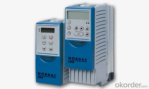
SK 500E - Modular frequency inverter
Following its introduction in the market the SK 500E product series has become successfully established and now the power range has been extended to 90kW. This extends the success factors of these components to a wider field of applications.
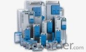
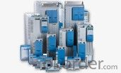
Modular compact inverter: SK 500E
With the SK 500E series of frequency inverters, Getriebebau NORD offers intelligent and costeffective drive solutions with scaleable equipment options, which are all fully compatible with regard to motor performance range, supply voltage and sizes. The basis for all models is a well-equipped basic unit with expansion possibilities through optional modules. SK 500E inverters are suitable for all application areas and can be easily adapted to specific requirements with plug-in technology units.
Performance grading:
The SK 500E product series offers a wide range of features which are necessary for application-specific drive solutions. Through different configuration levels, these can be used "in the same box". The inverters include the following functions, which are state-of-the-art for industrial applications.
"Safe stop" (STO) as per EN ISO 13849-1 Cat.4,
Performance level e EN 61508 SIL3CANopen interface on board
Incremental encoder input (TTL) on board
Absolute encoder via CANopen, SSi, BiSS, Hiperface, EnDat
POSICON positioning control
External 24V power supply for control board
Synchronous motor operation (PMSM)
PLC logic function
Sizes 1 - 4 (0.25 - 7.5 kW):
Frequency inverter SK 500E with integrated mains unit / SK 505E with external 24V supply
SK 500E / SK 505E basic equipment:
Sensorless current vector control (ISD control)
Line filter Class C2, Class C1 up to 5 m
Brake management, electro-mechanical motor brakes
Brake chopper for braking resistor
RS 232 PC diagnostic interface
4 switchable parameter sets
All normal drive functions
Automatic flux optimisation (energy saving function).
Process controller / PID controller
Consistent parameter structure
Simple to operate
All common field bus systems
Factory setting for parameters for standard applications
Scalable display values
High quality regulation and short reaction times
- Q: The failure of the step motor drive
- The LED is not bright Failure: the power supply is wrong; Low power supply voltage Solution: check the power connection. Boost voltage The motor does not turn, and the torque is not maintained Fault: the motor connection is not correct; Offline enable the RESET signal to be valid Solution: correct electrical wiring; Disable the RESET The motor doesn't turn, but it has torque Failure cause: no pulse input Solution: adjust pulse width and signal level The motor turns in the wrong direction Cause of failure: the power line sequence is wrong; The direction signal is wrong Solution: swap any two lines; Change direction setting Motor torque too small Cause of failure: the phase current is set too small; The acceleration is too fast; Motor blocked; The driver does not match the motor. Solution: set the phase current correctly; Decrease the acceleration; Eliminate mechanical failure; Change the appropriate driver.
- Q: How do the single-chip machine send pulse to the step motor drive? What's the pulse? The driver has a WC that receives the pulse!
- Need to see your stepper motor drives, have good stepper motor drive only need a thread to square wave pulse can drive the stepper motor rotation (and, of course, the positive and negative transfer control of a line and other lines) Some drives may require a few lines to encode (the code is in the specification) But generally the first kind is mostly, it is convenient to use
- Q: How does the servo motor drive work
- The power drive unit is the first through the three-phase full bridge rectifier circuit to the input three phase electricity or the municipal electricity to complete the rectifier, the corresponding direct current electricity. The three phase permanent magnet synchronous ac servo motor is driven by a three-phase sinusoidal PWM voltage inverter. The whole process of the power drive unit can be simply described as the ac-dc-ac process. The main topological circuit of the rectifier unit (ac-dc) is a three-phase fully bridge uncharged rectifier circuit.
- Q: How does the single-chip step motor drive connect
- The public is at the top of the > The pulse signal - - - >, a series of small resistors and a single chip output pulse The directional signal - - - > - a series of small resistance to a single chip With the above 3 lines can control the step motor moving, the electricity, the machine is automatically locked, if you still need to control stepping motor lock and release, the release signals to pick up a motor, connected with the pulse signal
- Q: How to learn more about stepping motors and stepping motors.
- When a motor is turned, the PWM subdivision drive is further studied. You can then learn about the drivers of various types of stepper motors, and the use of various types of drives. Then you can study how to reduce the vibration and noise of stepping motors. Then you can look at feedback control like PID.
- Q: How to set up the servo motor driver
- What brand are you using? There are many brands that are self-ordered.I hope my answer will help you
- Q: The voltage of the step motor driver?
- Input voltage affects the torque of stepping motor, the motor speed is proportional to the pulse frequency and startup if frequency is too high, stepping motor will not be able to spin, because the stator magnetic field changes too fast, the rotor can't keep up with, have to make the rotor has a acceleration process. Stop too, to have a slow process, do not suddenly stop pulse.
- Q: Can servo actuators control asynchronous motors?
- If it is to control the speed, torque accuracy is relatively high places there will be no ordinary motor, including electric spindle, you said the best way is to use servo motor. The main shaft is a high-speed motor, which is controlled by a transducer.
- Q: What is the principle of step motor drive?
- What are the advantages of drive segmentation? Why do you recommend using segmentation? The main advantages of drive segmentation are: eliminating the low frequency oscillation of the motor. Low frequency oscillation is a stepper motor (especially reactive motor) the inherent characteristics of the segment is the only way to eliminate it, if your stepper motor sometimes have to work in the resonance region (arc), select subdivision driver is the only option. The output torque of the motor is improved. In particular, the torque ratio of the three-phase reaction is about 30-40% higher than the non-break. Improved the resolution of the motor. By reducing the Angle of the step and increasing the evenness of the step distance, the "increase the resolution of the motor" is self-evident.
- Q: Why don't this step in the motor drive?
- The speed of the step motor is determined by the external control frequency and the segmentation, the first is to determine the subdivision, and to determine the control frequency.
Send your message to us
drive electronics SK 500E - Modular frequency inverter
- Ref Price:
-
- Loading Port:
- Shanghai
- Payment Terms:
- TT OR LC
- Min Order Qty:
- 3 unit
- Supply Capability:
- 50 unit/month
OKorder Service Pledge
OKorder Financial Service
Similar products
Hot products
Hot Searches
Related keywords

