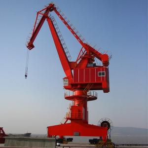
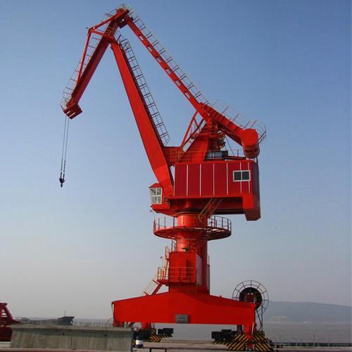
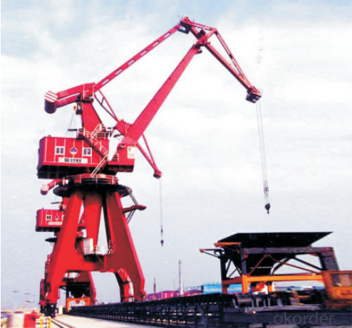
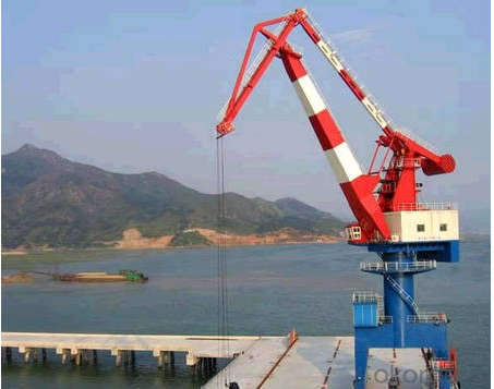
Portal Crane,Frequency vecyor control,Electric power feedback technology
- Loading Port:
- China main port
- Payment Terms:
- TT OR LC
- Min Order Qty:
- 1 set
- Supply Capability:
- 1 set/month
OKorder Service Pledge
OKorder Financial Service
You Might Also Like
Specification
Profile
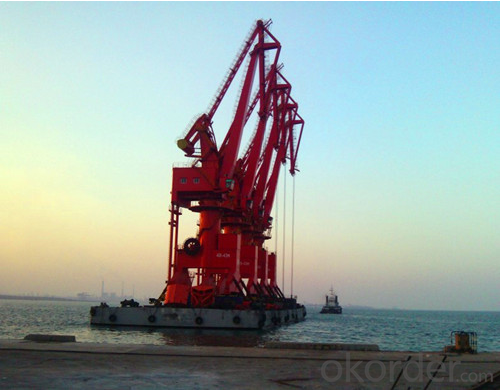
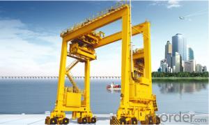
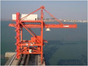
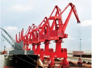
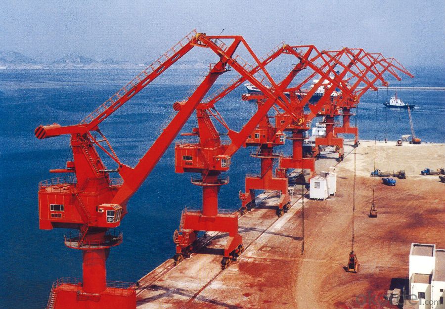
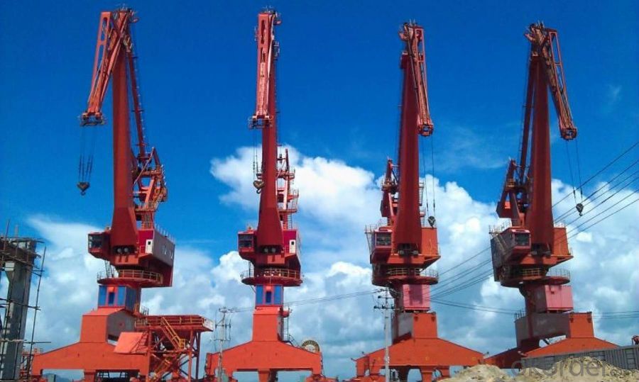
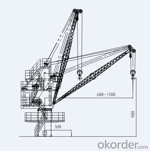
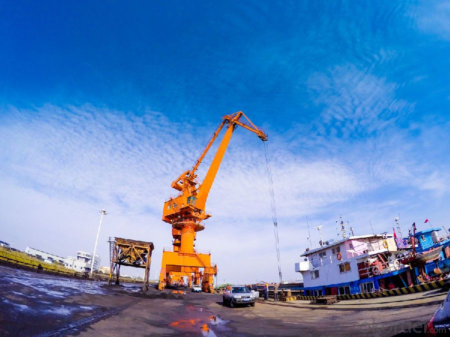
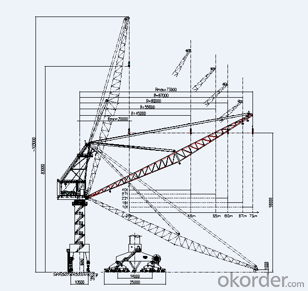
As a kind of crane, the portal crane is widely used in harbor, wharf, station, stockyard and other open yard. At these places, the ships and vehicle need a kind of high-efficiency equipment to handle and transfer the materials, which aims to quicken the turnover of the ships and vehicle. Portal crane has following good performance, such as, advanced performance, high-efficiency operation, compact structure, balance working system, comfortable operation, reliability and stability, convenient maintaining, good appearance and other advantages. Also, it can make full use of the harbor, wharf and limit site. It can meet the requirement of the access of the vehicle and the ship with the empty load and full load. Especially, it is suitable for common wharf, which can complete the handling the containers, sundries and bulk material along the front of the wharf. It is a kind of low investment and effective lifting equipment.
On the gate type engine base, it loads rotating part of the portal crane. In fact, the gate type engine base is the main bearing part. Under the gate type engine base, it is equipped with the traveling mechanism, which can run on the rail which is set on the ground. On the rotating part, it is equipped with four mechanisms, such as cantilever and lifting mechanism, rotating mechanism, jib lubbing mechanism. These four mechanisms can realize cooperative work. Then, by means of these four parts, it can realize the installation of the body of the ship and equipment,or it can handle the material.
The structure of the portal crane
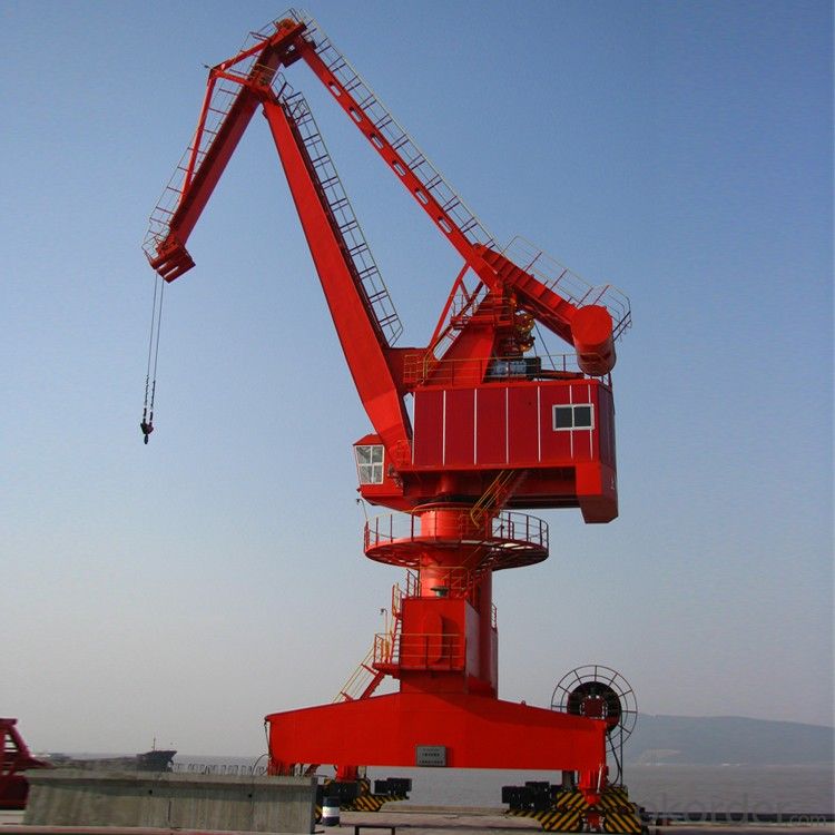
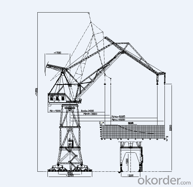
The portal crane is mainly divided into two parts, the upper rotating part and the bottom traveling parts.
The upper rotating part include following parts, such as, jib system, propeller strut, rotating platform, cab, machine room and etc. In the machine room, it is installed with lifting mechanism, jib lubbing mechanism and rotating mechanism. The bottom traveling part includes gate seat and traveling mechanism.
Technical specifications
1030 | |||
Lifting capacity | t | 10 | |
Working class of whole machine | A7 | ||
Lifting height | Above the interarea | m | Grab 16 Hook 25 |
Below the interarea | Hook 15 | ||
Working radius | Max. | 30 | |
Min. | 8.5 | ||
Lifting mechanism | Working class | M7 | |
Lifting speed | m/min | 60 | |
Luffing mechanism | Working class | M6 | |
Radius changing speed | m/min | 52 | |
Rotating mechanism | Working class | M6 | |
Rotating speed | r/min | 1.51 | |
Traveling mechanism | Working class | M4 | |
Traveling speed | m/min | 27 | |
Power source | Three phase AC 50Hz 380V | ||
Gauge/base distance | m | 10.5/10.5 | |
Max. Turning radius | 30 | ||
Turning radius of after section | ~7.8 | ||
Max.wind pressure during operation | N/m | 250 | |
Max.wind pressure out of operation | 1000 | ||
Max.wheel load during operation | KN | 220 | |
Recommended rail | P50 | ||
Installed capacity | kw | 350 | |
Technical specifications
Technical specification | 1633 | ||
Lifting capacity | t | Grab16 Hook16/25 | |
Working class of whole machine | A7 | ||
Lifting height | Above the interarea | m | Grab 20 Hook 28 |
Below the interarea | 16 | ||
Working radius | Max. | Grab 33 Hook 33/23 | |
Min. | 9.5 | ||
Lifting mechanism | Working class | M7 | |
Lifting speed | m/min | 50 | |
Luffing mechanism | Working class | M6 | |
Radius changing speed | m/min | 50 | |
Rotating mechanism | Working class | M6 | |
Rotating speed | r/min | 1.51 | |
Traveling mechanism | Working class | M4 | |
Traveling speed | m/min | 25 | |
Power source | 3-phase AC 50Hz 380V | ||
Gauge/base distance | m | 10.5/10.5 | |
Max. Turning radius | 33 | ||
Turning radius of after section | ~8.5 | ||
Max.wind pressure during operation | N/m | 250 | |
Max.wind pressure out of operation | 1000 | ||
Max.wheel load during operation | KN | 250 | |
Recommended rail | P50 | ||
Installed capacity | kw | 450 | |
Technical specifications
Technical specification | 3055 | ||||
Working class of whole machine | A5 | ||||
Lifting capacity | Lifting capacity | t | Main hook | Auxi.hook | |
30 | 10 | 5 | |||
Scope | m | 15~17 | 15~50 | 19~55 | |
Lifting height | 50 | 50 | |||
Working radius | Max. | 55 | 50 | ||
Min. | 19 | 15 | |||
Speed of mechanism | Lifting speed | m/min | 10(20,<12) | 20(40,<2t) | |
Radius changing speed | ~10 | ||||
Rotating speed | r/min | 0.24 | |||
Traveling speed | m/min | 30 | |||
Power source | 3-phase AC 50Hz 380V | ||||
Gauge/base distance | m | 10.5/12 | |||
Head room of portal | ~10 | ||||
Turning radius of after section | ~15 | ||||
Turning radius of after section of turnplate | ≤12 | ||||
Max.wind pressure during operation | N/m | 250 | |||
Max.wind pressure out of operation | 1000 | ||||
Max.wheel load during operation | KN | 250 | |||
Recommended rail | P50 | ||||
Installed capacity | kw | 220 | |||
Technical specifications
Technical specification | 4073 | ||||||
Working class of whole machine | A4 | ||||||
Lifting capacity | Lifting capacity | t | 40 | 27 | 22 | 16 | 10 |
Scope | m | 20~45 | 20~55 | 20~60 | 20~67 | 20~73 | |
Lifting height | 45 | ||||||
Working radius | Max. | 73 | |||||
Min. | 20 | ||||||
Speed of mechanism | Lifting speed | m/min | 0.2~10 | ||||
Radius changing speed | 0.2~10 | ||||||
Rotating speed | r/min | 0.3 | |||||
Traveling speed | m/min | 30 | |||||
Power source | 3-phase AC 50Hz 380V | ||||||
Gauge/base distance | m | 10.5/14 | |||||
Head room of portal | 8.06 | ||||||
Turning radius of after section | ~9.4 | ||||||
Turning radius of after section of turnplate | N/m | 250 | |||||
Max.wind pressure during operation | 1000 | ||||||
Max.wind pressure out of operation | KN | 400 | |||||
Recommended rail | P50 | ||||||
Installed capacity | kw | 350 | |||||
The four main parts of the portal crane
Lifting mechanism
As a kind of lifting mechanism, it is used to move the material upward and downward. Generally speaking, by means of changing the spinning direction, it can control the crane lifting the material upward and downward. The lifting mechanism is made up of drive mechanism, coiling system of steel wire rope and fetching mechanism.(The fetching device of the portal crane, commonly, contains hook and grab.)
Jib lubbing system
Making use of the jib lubbing mechanism, the portal crane can change the handling route of the material to complete the loading and unloading the material. Under loading, the amplitude of variation of the jib is called as operation luffing mechanism. Without loading, the amplitude of variation is called as non-operation luffing mechanism. In order to enhance the productivity, the portal crane is widely used operation luffing mechanism.
Rotating mechanism
The rotating mechanism of the portal crane is used to move the lifted material horizontally along the circular arc. Combining with the lifting mechanism and luffing mechanism, it can move the lifted material to the any positions in the luffing range. The rotating mechanism is mainly made up of two part, such as, the rotating and supporting device and the drive part for making the rotating part spinning.
Traveling mechanism
The traveling mechanism is mainly up of three parts which includes traveling supporting device, traveling drive mechanism and safety mechanism. The supporting device includes beam, wheel and lock shaft. The drive device includes electric motor, brake and reducer. The safety mechanism traveling mechanism includes rail clamping device, buffering, normal limit switch, sweeping rail plate and etc.
Technical specifications
Technical specification | 12065 | ||||
Working class of whole machine | A5 | ||||
Lifting capacity | Lifting capacity | t | Main hook | Auxi.hook | |
120 | 40 | 20 | |||
Scope | m | 24~33 | 24~60 | 28~65 | |
Lifting height | 60 | 60 | |||
Working radius | Max. | 60 | 65 | ||
Min. | 24 | 28 | |||
Speed of mechanism | Lifting speed | m/min | 6(12,<48) | 15(30,<8) | |
Radius changing speed | ~10 | ||||
Rotating speed | r/min | 0.24 | |||
Traveling speed | m/min | 30 | |||
Power source | 3-phase AC 50Hz 380V | ||||
Gauge/base distance | m | 13/16 | |||
Head room of portal | ~13 | ||||
Turning radius of after section | ~17 | ||||
Turning radius of after section of turnplate | ≤15 | ||||
Max.wind pressure during operation | N/m | 250 | |||
Max.wind pressure out of operation | 1000 | ||||
Max.wheel load during operation | KN | 450 | |||
Recommended rail | QU120 | ||||
Installed capacity | kw | 450 | |||
Technical specifications
GQ0515 | |||
Working class of whole machine | A6 | ||
Lifting capacity | t | 5 | |
Lifting height | Above the interarea | m | 9 |
Below the interarea | 7.5 | ||
Working radius | Max. | 15 | |
Min. | 6 | ||
Speed of mechanism | Lifting speed | m/min | 25 |
Radius changing speed | 22 | ||
Rotating speed | r/min | 1.36 | |
Power source | 3-phase AC 50Hz 380V | ||
Turning radius of after section of turnplate | m | ≤4 | |
Max.wind pressure during operation | N/m | 250 | |
Max.wind pressure out of operation | 1000 | ||
Technical specifications
Technical specification | GQ1615 | ||
Working class of whole machine | A6 | ||
Lifting capacity | t | 16 | |
Lifting height | Above the interarea | m | 6 |
Below the interarea | 6 | ||
Working radius | Max. | 15 | |
Min. | 6 | ||
Speed of mechanism | Lifting speed | m/min | 20 |
Radius changing speed | 40 | ||
Rotating speed | r/min | 1.5 | |
Power source | 3-phase AC 50Hz 380V | ||
Turning radius of after section of turnplate | m | ≤4 | |
Max.wind pressure during operation | N/m | 250 | |
Max.wind pressure out of operation | 1000 | ||
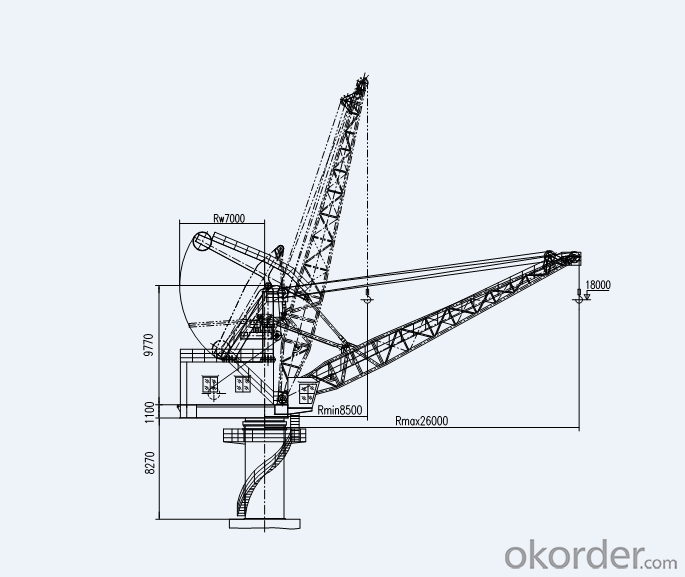
Technical specifications
Technical specification | GQ3526 | ||
Working class of whole machine | A6 | ||
Lifting capacity | t | 35 | |
Lifting height | Above the interarea | m | 18 |
Below the interarea | 8 | ||
Working radius | Max. | 26 | |
Min. | 8.5 | ||
Speed of mechanism | Lifting speed | m/min | 18 |
Radius changing speed | 15 | ||
Rotating speed | r/min | 1 | |
Power source | 3-phase AC 50Hz 380V | ||
Turning radius of after section of turnplate | m | ≤7.5 | |
Max.wind pressure during operation | N/m | 250 | |
Max.wind pressure out of operation | 1200 | ||
Send your message to us
Portal Crane,Frequency vecyor control,Electric power feedback technology
- Loading Port:
- China main port
- Payment Terms:
- TT OR LC
- Min Order Qty:
- 1 set
- Supply Capability:
- 1 set/month
OKorder Service Pledge
OKorder Financial Service
Similar products
Hot Searches
Related keywords
