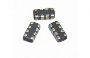
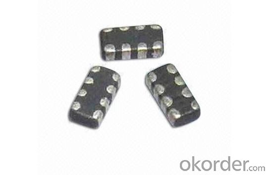
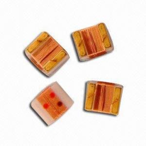
SMD Multilayer Ferrite Chip Bead 0805
- Ref Price:
-

- Loading Port:
- China Main Port
- Payment Terms:
- TT or LC
- Min Order Qty:
- 4000 Pieces pc
- Supply Capability:
- 4000 Pieces per Day pc/month
OKorder Service Pledge
OKorder Financial Service
You Might Also Like


1.SMD multilayer ferrite chip bead
2.High Impedance Characteristics
3.size: 0805
4.RoHs
5.competitive price
Features:
*Low crosstalk/DCR, high reliability
*Low crosstalk between adjacent circuits
*Single MZA series chip provides noise attenuation for four lines, ideal for various highly miniaturized I/D lines
*Internal electrodes feature low DC resistance, minimizing wasteful power consumption
*Electroplated terminal electrodes accommodate flow and reflow soldering
*Mololithic structure ensures high reliability
*Operating temperature range from -25 to 85℃
Applications:
*High-frequency noise counter measured in computer
*Printers
*Portable telephones and other equipments
*VCRs
*Televisions
- Q:I have been searching for inductors for a 2nd order crossover and can't find exact matches, only close matches. How much will my crossover be affected if I use a 3.3 mH inductor instead of a 3.2 mH inductor? What about using a 5.0 mH inductor instead of a 5.2 mH inductor for the second one? Will it be that noticeably and undesirably affected?
- The tolerance on the inductors is likely to be ±5%; the tolerance on the capacitors is more likely to be ±10%. 3.3mH is out by +0.3% from 3.2mH and 5.0mH is out by -4% from 5.2mH. It'll probably sound fine. You could even add a few extra turns (1 more for every 50: the inductance is proportional to the number of turns squared, so increasing turns by 2% will increase inductance by double that, i.e. 4%) on the 5mH inductor, or stick a piece of ferrite rod down the middle if it doesn't.
- Q:An inductor that has an inductance of 24 H and a resistance of 41 ? is connected across a 120 V battery. What is the rate of increase of the current at 0 s. Answer in units of A/s.What is the rate of increase of the current at 0.7 s.Answer in units of A/s.
- Back emf,e L.di/dt where L inductor, di/dt is the rate of change of current. And Z^2 R^2 + XL^2 where Z is impedance, R is the resistance and XL is the inductive reactance. Z^2 41^2 + (2pi*60*24)^2 [Assuming line frequency, f 60 Hz) Z^2 1681 + 8985.6 10666.5 Z 103.27 ohms. Now the total current ,I 120/ Z 120/ 103.27 1.162 amps. Again, T L/R where T Time constant 24/41 .58 sec which is one time constant' In this period, the current flows 63% of the full current 1.162 amp .73 amps. For full current of 1.62 to flow is the time, 5T .58*52.9 sec.And discharge current is 37% 1.162*.37 .59 amps, During this period, back emf occurs Hence the back emf,e .59*sqrt8985.6 or,e .59*94.7 55.8 volts at this voltage, then at .7 sec, di/dt .59/.7 .84 amp/sec at 0 sec, di/dt .84/0 infinity that is like a short circuit current. I think this is the answer. Thank you.
- Q:A series circuit contains a resistor with R 24 ohms, an inductor with L 2 H, a capacitor with C 0.005 F, and a generator producing a voltage of E(t) 12 sin(10t). The initial charge is Q 0.001 C and the initial current is 0. Find the charge at time t.Q(t) ??
- First thing to realize is that this circuit is in resonance. The characteristic frequency is equal to 1/sqrt(LC) 1/sqrt(2*.005) 10 This means the driving source won't provide net new charge to the capacitor and we can look at this in two pieces so for the output across the capacitor we have v-out 1/jωC/(R+jωL+1/(jωC))*v-in 1/(1-ω^2LC+jωRC) When we plug in values we get v-out1/(1-10^2*(2*0.005)+j10*24*.005) v-out1/(1-1+1.2j)*v-in -j/1.2*12sin(10t) 10sin(10t-π) so the change in Q across the capacitor from the driven source will be Q(t)-driven 0.005*10sin(10t-π) 0.0510sin(10t-π) C now we have to look at the initial conditions with a voltage of 0.2 V stored in the capacitor. We'll short out the driven source and solve for the decay in voltage through the resistor and inductor Because there is in essence a DC voltage stored on the capacitor and discharged through the resistor, the inductor has no role. The voltage discharge is 0.2exp(-t/RC)0.2exp(-8.33t). The charge is just this multiplied by C. or 0.2*0.005exp(-8.33t)0.001exp(-8.33t) the total will be Q(t)0.0510sin(10t-π)+0.001exp(-8.33t)
- Q:A circuit consists of 6ohm resistor; an inductor of 18 mH is connected in parallel. The totalcurrent ?owing towards the circuit is given by: I 4.5 Sin wt +1.7 Sin (3wt +25°) + 0.75 Sin (5wt -35°) AThe fundamental frequency is 50 Hz. Determine:5.1 An expression for the applied voltage5.2 The true power ofthe circuit5.3 The overall power factor ofthe circuit.
- This is no different from any other problem like this. The fact that the current has 3 terms doesn't change anything, except the voltae will also have 3 terms.
- Q:Also ,when there are two capacitors and two inductors in a circuit,how do I calculate the resonant frequency ?
- Inductance of a wire is ??L/8π ?? is the magnetic constant 1.2566e-6 H/m (or T·m/A) L is length in meters Inductance of a hollow cylinder is (??L/2π)(ln((2L/a)–1) a is the radius. thickness is negligible. 2) depends on how they are connected. Combine the two caps as series or parallel, ditto inductors.
- Q:If a full wave rectification of an A.C. current flows through a closed circuit in series a coil of wire wound around a solenoidal core, what happens to the current in the overall circuit?
- What is the overall circuit? We would need more details to answer this.
- Q:A 26.0 mH inductor has a reactance of 1.80 k. (a) What is the frequency of the ac current that passes through the inductor? ____Hz(b) What is the capacitance of a capacitor that has the same reactance at this frequency? ___ F(c) The frequency is tripled, so that the reactances of the inductor and capacitor are no longer equal. What is the new reactance of the inductor?____ k(d) What is the new reactance of the capacitor?___ k
- ok for the first one: reactance is 2pifL Xl reactance Solve for f which is frequency b. then u use 1/2pifC Xc for part b, and use this equation to get C c. Just do what it says for c and d. and use the above equations.
- Q:A battery (V-9V) is connected with a resistor R1000 ohms and an inductor L 0.5mH. The circuit initially contains an open switch and at t 0, the switch is closed.a) what is the time circuit?b) Determine the Maximum current flowing in the circuit
- The time constant for an RL circuit L/R (remember that L*Amps/second Amps*R so L/R has units of seconds). L/R 0.5e-3/1e3 0.5e-6 s R/L 2e6 2,000,000 After a long time an inductor is modeled as a short circuit when the current is a maximum V/R V/R 9/1000 9e-3 A 9 ma. iL(t) 9ma*[1-e^-t/(L/R)] 9ma*[1-e^-Rt/L] 9ma*[1-e^-2,000,000*t] After 5 time constants 2.5e-6 e^-2e6*2.5e-6 e^-5 iL(5*L/R) iL(2.5e-6) 9ma*(1-e^-5) 8.94ma which is 99.33% it's maximum value after only 2.5μs
- Q:A 9.5 V battery, a 4.92 resistor, and a 9.7 H inductor are connected in series:(a) After the current in the circuit has reached its maximum value, calculate the power being supplied by the battery.(b) Calculate the power being delivered to the resistor.(c) What is the power being delivered to the inductor?(d) What is the energy stored in the magnetic field of the inductor?
- a million - particular. many times extra desirable than one moving interior a similar path. 2 - a moving value (a modern) continually generates a magnetic field in accordance to Lorentz regulation. 3 - a variable magnetic field induces a modern right into a conductor. 4 - possibly you meant capacitors, not conductors. a capacitor is a gadget in a position to generate a persevering with electric field. an inductor is a gadget in a position to generate a persevering with magnetic field.
- Q:a fully charged capacitor is connected to an inductor and a resistor. what is the value of tfe charge on the capacitor when time becomes large?
- Depends on what the total circuit looks like. If both ends of the capacitor are connected to each other thought the resistor, and maybe the inductor, then the large-time charge will be zero.
1. Manufacturer Overview |
|
|---|---|
| Location | Guangdong,China (Mainland) |
| Year Established | 2010 |
| Annual Output Value | US$10 Million - US$50 Million |
| Main Markets | North America; South America; Eastern Europe; Southeast Asia; Africa; Oceania; Mid East; Eastern Asia; Western Europe |
| Company Certifications | ISO 9001:2000 |
2. Manufacturer Certificates |
|
|---|---|
| a) Certification Name | |
| Range | |
| Reference | |
| Validity Period | |
3. Manufacturer Capability |
|
|---|---|
| a)Trade Capacity | |
| Nearest Port | |
| Export Percentage | 41% - 50% |
| No.of Employees in Trade Department | |
| Language Spoken: | |
| b)Factory Information | |
| Factory Size: | |
| No. of Production Lines | |
| Contract Manufacturing | OEM Service Offered Design Service Offered Buyer Label Offered |
| Product Price Range | |
Send your message to us
SMD Multilayer Ferrite Chip Bead 0805
- Ref Price:
-
- Loading Port:
- China Main Port
- Payment Terms:
- TT or LC
- Min Order Qty:
- 4000 Pieces pc
- Supply Capability:
- 4000 Pieces per Day pc/month
OKorder Service Pledge
OKorder Financial Service
Similar products


New products


Hot products

Hot Searches
Related keywords

