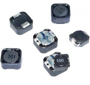
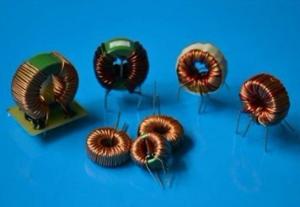
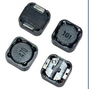
PBH/PBL SERIES SMD Power Inductor
- Ref Price:
-

- Loading Port:
- China Main Port
- Payment Terms:
- TT or LC
- Min Order Qty:
- 3000 Pieces pc
- Supply Capability:
- 20,000 Pieces per Day pc/month
OKorder Service Pledge
Quality Product, Order Online Tracking, Timely Delivery
OKorder Financial Service
Credit Rating, Credit Services, Credit Purchasing
You Might Also Like
Features:
1.SMD Power Inductor
2.Magnetic shieled surface mount inductor with high current rabing low D.C resistance
3.Excellent terminal strength
4.Packed in embossed carrier tape and can beused by automatic mounting machine.
5.Various hogh power inductors are superior to be high saturation for suiface mounting
Applications:
Power supplu for VTR,OA equipment Digital camera, LCD television set notebook PC, portable
communication equip,ents, DC/DC converters, etc.
- Q:After the switch in the following circuit has been closed for a long time (tinfinity), what is the current through L1?Also, after the switch in the circuit in the circuit has been open for t500 microseconds, what's the current through L2?How do i find the current? Please show me or give me instructions how as this will help me in the future.
- the current initially is 10v / 500 ohms 0.02 amp When you open the switch, the current will eventually decrease to 10v / 1000 0.01 amp It decays exponentially from the initial to the final value with a time constant, T, of L/R 0.25 / 1000 250 usec i(t) 0.01 + 0.01 e^(-t / T) i(500) 0.01 + 0.01e^(-500/250) 0.01 + 0.01e^(-2) 0.01135 amp
- Q:whats the diffrence between a inductor with a medal and a normal inductor?
- Induction with a metal core produces a far stronger force than an inductor with an air core. The metal consolidates the magnetic field lines so they are greatly intensified over just a air core inductor
- Q:A 4 mH inductor is connected to an AC voltage source of 149 V rms. If the rms current in the circuit is 0.83 A, what is the frequency of the source?
- Use the equation X 2pi*f*L. You are given X indirectly, through V and I. Since I V/X, X V/I. Once you solve for X you can put this in the first equation and solve for f. X V/I 149/.83 179.52 X/(2pi*L) f 179.52/(2pi*.004) 7142.797 Hz
- Q:If the design of an inductor calls for 80 turns of .5mm wire around a 40mm OD iron torroidal core, how do I calculate the inductance in mH or uH?This isn't a homework problem, I'm building a circuit that calls for this inductor and I want to know what the resulting inductance is so that I don't have to build the inductor myself. I want to purchase one pre-wound.
- Inductance is given by Luo ur N^2 Ae/le where uo4 pi E-7, urrelative permeability, Nnumber of turns, Ae is cross sectional area of core [m^2], lelength of core [m].
- Q:A 440 resistor, 45 ?F capacitor, and 810 mH inductor are each connected across 6.3 V rms, 60 Hz AC power sources. Find the rms current in each path.a) resistorb) capacitorc) inductorI keep getting the wrong answer I am using all the right formulas can someone let me know how to do this problemplease!!!
- They can all be considered separately since they don't interact. A. I(R) V/R 0.0143182 A B. w 2pi*60 376.99 rad/s X(C) 1/(wC) 58.9463 ohms; I(C) V/X(C) 0.106877 A C. X(L) wL 305.363 ohms; I(L) V/X(L) 0.026312 A
- Q:An inductor of 0.5 H and a resistance of 1.2 K ohms are connected in series with an ideal source with e.m.f. 6 V. The current expression in the circuit as a function of time is: 5.0*10^-3(1-e^-2398t ) . Calculate the potential difference across the inductor at t 0.417 ms. the correct answer is: 2.21v . can you tell me how to do it? :)
- Set t 0.417*10^-3 in the formula given. That gives you the current at t 0.417 ms ie 3.16*10^-3 ma In the 1.2k resistor, that drops v i*r 1.2*10^3*3.16*10^-3 volts ie 3.79 volts That leaves (6 - 3.79) volts ie 2.21 volts across the inductor.
- Q:A series ac circuit contains a 170ohm resistor, a 15.0mH inductor, a 3.50 uF capacitor, and an ac power source of voltage amplitude 45.0V operating at an angular frequency of 360 rad/s.I found the power factor to be .211 and the avg power to be .265W. I can't seem to find the avg power to the resistor, capacitor, and inductor.
- Neither the inductor nor the capacitor will absorb power, so all the real power is delivered to the resistor.
- Q:Can you please help me about this question?
- This is an absurd question, as the source resistance of the step input source e(t) is shown as zero.In that case, the source will dictate the voltage across C and voltage across C will always be equal to source voltage. You could pretend that source has a resistance. In that case, output is a voltage that decays as exp[-t/(RC)] where R is source resistance.It builds up with a much lesser time constant if R of L is very low.
- Q:how to relate the amount of turns for inductor of crystal radio to its performance?
- They can be overlapping if you do not use the traditional slider on the coil to tune stations. The slider needs to be able to adjust the length of the coil to change frequency and if the coils are overlapping you would limit its range of tuning. In some crystal radio configurations a variable capacitor is used for selecting the frequency and these usually have overlapping windings. Most crystal radio enthusiasts agree that the sensitivity and selectivity is better with a single wound air core coil.
- Q:2.In the figure, after the switch is closed at time t0, the emf of the source is automatically adjusted to maintain a constant current I through S. a) Find the current through the inductor as function of time. b) At what time the current through the resistor equal to the current through the inductorthe circuit looks like this:a constant current source with a switch in series and then splits into a resistor and inductor in parallel
- the means in an inductor is proportional to the oblong of the present. At area the present it holds a million/4 the quantity of means. It held 40 J on the commencing, it now holds 10 J so the distinction is 30 J
Our products have highest quality and competitive prices.Our well-equipped facilities and excellent quality control throughout all stages of production enable us to guarantee total customer satisfaction. As a result of our high quality products and outstanding customer service, we have gained a global sales network.
1. Manufacturer Overview |
|
|---|---|
| Location | Guangdong,China (Mainland) |
| Year Established | 2010 |
| Annual Output Value | US$10 Million - US$50 Million |
| Main Markets | North America; South America; Eastern Europe; Southeast Asia; Africa; Oceania; Mid East; Eastern Asia; Western Europe |
| Company Certifications | ISO 9001:2000 |
2. Manufacturer Certificates |
|
|---|---|
| a) Certification Name | |
| Range | |
| Reference | |
| Validity Period | |
3. Manufacturer Capability |
|
|---|---|
| a)Trade Capacity | |
| Nearest Port | |
| Export Percentage | 41% - 50% |
| No.of Employees in Trade Department | |
| Language Spoken: | |
| b)Factory Information | |
| Factory Size: | |
| No. of Production Lines | |
| Contract Manufacturing | OEM Service Offered Design Service Offered Buyer Label Offered |
| Product Price Range | |
Send your message to us
PBH/PBL SERIES SMD Power Inductor
- Ref Price:
-
- Loading Port:
- China Main Port
- Payment Terms:
- TT or LC
- Min Order Qty:
- 3000 Pieces pc
- Supply Capability:
- 20,000 Pieces per Day pc/month
OKorder Service Pledge
Quality Product, Order Online Tracking, Timely Delivery
OKorder Financial Service
Credit Rating, Credit Services, Credit Purchasing
Similar products


New products

Hot products

Hot Searches

