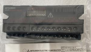


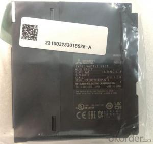
Organic Materials DC Motor Newest Mitsubishi Melsec AJ65SBTB2N-8S
- Ref Price:
-

- Loading Port:
- Shanghai
- Payment Terms:
- TT OR LC
- Min Order Qty:
- 1 kg
- Supply Capability:
- 2000 kg/month
OKorder Service Pledge
OKorder Financial Service
You Might Also Like
Item specifice
A small remote I / O module used as a remote I / O station for control and
communication links (hereinafter referred to as "CC link"). Its features are as
follows:
(1) The small remote I / O module reduces the volume while maintaining all the
functions of the traditional module.
(2) More models of small remote I / O module series
Waterproof terminals are added to the small remote I / O module series for CC
link system. Along with the traditional terminal block type, there are also
quick connector type modules and FCN connectors
Type and connector type, now there are five models of products.
In addition to the traditional 16 point and 32 point remote I / O modules, an
8-point type is added, so that users can choose the most appropriate module
according to their own purpose and environment.
(3) The 4-wire small remote I / O module is easy to connect to the 4-wire
sensor.
It can be easily connected to the 4-wire sensor through the common pin provided
on each plug. It is not necessary to install relay terminal block.
For 4-wire small remote I / O modules, one sensor is connected to one plug.
Therefore, the sensor can be changed through the plug, reducing the operation
steps.
(4) The terminal block connection makes it easy to connect 2-wire and 3-wire
sensors or loads.
Because the terminal block connection allows the connection of 2-wire and 3-
wire sensors or loads, there is no need for a common connector, which makes the
connection easier.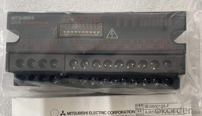
(5) Minimize wiring
(a) Terminal block module
By using the self tightening screw on the terminal block, the wiring steps can
be significantly reduced.
(b) Quick connector module, connector module
The wiring steps can be significantly reduced by using the parallel wire
pressure wiring method (without welding, stripping the shielding layer and
screwing).
(c) FCN connector type module
Wiring steps can be significantly reduced by using 40 pin connectors for I / O
parts.
(6) Waterproof remote I / O module has improved waterproof and oil proof effect
The waterproof remote I / O module adopts a protective structure compatible
with IP67, which can be used more safely in the presence of water and oil.
(7) Up to 64 remote I / O modules can be connected
In CC link system, each master station can connect up to 64 remote I / O modul
Since each remote I / O module accounts for 32 points, a maximum of 2048 link
points can be set.
(8) The module can be replaced without stopping the CC link system
The dual block terminal block used for CC link cable connection can be used to
replace the module without stopping the operation of CC link system.
(9) It can be installed directly on the machine
The terminal block type remote I / O module can be installed directly on the
machine because there is a live area protected by a finger guard in the area
above the terminal block.
(10) The module can be installed in 6 directions
Small remote I / O modules can be installed in 6 different directions. (there
are no restrictions on the installation direction.)
The module can also be installed with DIN rail.
(11) Transistor output module with improved protection function
Transistor output module in order to achieve better module protection ability,
as a standard model, its design adopts short-circuit protection, overload
protection, overheating protection and overvoltage protection.
Therefore, the reliability of PLC system has been further improved.
- Q:I think I understand this more now after looking at my notes a little more. I need to turn them into polar form to make the division easier. Then I can put it back into the original form after.
- The magnitude of the circuit impedance is equal to the inductive reactance provided by the inductance: L X ωL, but ω 200 rad/s so that X 200(0.25) 50 ohm while V 100 volts the phasor current for the circuit: I V/Z where V is the voltage phasor V 100 angle 0? and the complex impedance: Z jX j50 Therefore: I 100/(jX) -j2 2 angle -90? The phasor current lags the phasor voltage by 90?.
- Q:A series circuit consisting of an inductor of negligible resistance and a pure resistor of 12Ω is connected to a 30V, 50Hz AC supply. If the current is 2A, calculate: (a) the PD across the resistor (b) the PD across the inductor (c) the inductance of the inductor (d) the phase angle between applied voltage and current. (e) the impedance of the circuit
- (a) PD 2A X 12 Ohm 24 Volts (b) Z 30V/2A 15 Ohm Xl (15 Ohm) X sin(arc cos 12/15) 9 Ohm PD across inductor 2A x 9 Ohm 18 Volts (c) 9 Ohm (6.28) x (50) x inductance Inductance 9 / 314 28.7mH (d) Phase angle arc tan Xl/R arc tan 9/12 36.87 degrees (e) Impedance 30V/2A 15 Ohm
- Q:Find the induced emf when the current in a 47.5 mH inductor increases from 0 to 521 mA in 17.1 ms. Any help would be appreciated. If you are able to answer this one, please show your work. Thanks!
- v L di/dt di/dt is the rate of change of current, or put another way, the change in current over time. You can see that this is (0.521 - 0)/(0.017 - 0) If the units are Amperes, Seconds, and Henrys on the right, the formula will produce Volts on the left.
- Q:I just want to know if i got the general idea of inductors downthey store current energy because when a magnetic field is running through the coils, a current is induced and adds up proportionally to the number of coils? does that explain how inductors store energy?
- How Inductors Work
- Q:An inductor and a resistor are in series with a sinusoidal voltage source. The frequency is set so that the inductive reactance is equal to the resistance. If the frequency is increased, then(A) VL 2VR(B)VL VR(C) VL VR(D)VR VL
- C. Inductive reactance increases with frequency. Z 2piFL.
- Q:A 94 mH inductor is connected to a outletwhere the rms voltage is 127 V and the frequency is 42 Hz.Determine the energy stored in the inductorat t 8.9 ms, assuming that this energy iszero at t 0.Answer in units of J
- Do inductors store energy? Man! I dont think so!
- Q:If a full wave rectification of an A.C. current flows through a closed circuit in series a coil of wire wound around a solenoidal core, what happens to the current in the overall circuit?
- Assuming you've got an AC source (wall plug) hooked up to a bridge rectifier (with or without transformer), the output will be a rectified sinewave. If you apply a rectified sine to an inductor, coil, solenoid, etc, current will flow in one direction only, and the inductor will attempt to smooth out the drops in voltage, and oppose any change in current. This is similar to placing a capacitor in parallel, and basically filters out any AC harmonics, leaving a cleaner DC output. Bottom line: current gets filtered to produce cleaner DC.
- Q:An inductor has an impedance of 31.0 Ω and a resistance of 20.5 Ω at a frequency of 47.5 Hz. What is the inductance? (Model the inductor as an ideal inductor in series with a resistor.)? (in mH)
- Impedance Z √(R? + X??) 31? 20.5? + X?? X? 23.25 ohms X? 2πfL 23.25 2π(47.5)L L 0.0779 H or 78 mH .
- Q:A 12.6-V battery is in series with a resistance of 0.330 Ω and an inductor. I got part a right, but I can't seem to figure out the rest. help please. a) After a long time, what is the current in the circuit?I(tinfinity) 38.1 A(b) What is the current after one time constant?I(tτ) AHow is the time constant defined for an RL series circuit? How does the current change as a function of time in such a circuit (c) What's the voltage drop across the inductor at this time?ΔVL VUse Kirchoff's Loop rule to describe the relative sizes of the potential differences across the battery, inductor, and resistor.(d) Find the inductance if the time constant is 0.110 s.L H
- b) Current is given by i (E/R)*(1 - e^(-t/tL)) where tL is the inductive time constant. If t tL then i (E/R)*(1 - e^(-1)) You can crank that out. In an RL series circuit, tL L/R c) If the current is i, the voltage across it is i*R. The voltage across the circuit is E. So the voltage across the inductor is E - i*R. d) tL L/R 0.110 s Solve for L. The L H threw me at first -- I think it's telling you that the units are henries.
- Q:A 100 mH inductor is in series with a resistance R 1.1 Ω.If a current I Acos(ωt) is applied, to this circuit, find the frequency at which:The voltage amplitude across the resistance is 1% of the voltage amplitude across the inductor.Please show me how to do this question with the working out and explanation because i have tried for hours and am getting very annoyed i really need help.thanks
- It is where I * R I * ω * L / 100 or R 2 pi f * L / 100 or f 100 * R / (2 * pi * L) 110 / (6.2832 * 0.10) 175.1 Hz
1. Manufacturer Overview |
|
|---|---|
| Location | |
| Year Established | |
| Annual Output Value | |
| Main Markets | |
| Company Certifications | |
2. Manufacturer Certificates |
|
|---|---|
| a) Certification Name | |
| Range | |
| Reference | |
| Validity Period | |
3. Manufacturer Capability |
|
|---|---|
| a)Trade Capacity | |
| Nearest Port | |
| Export Percentage | |
| No.of Employees in Trade Department | |
| Language Spoken: | |
| b)Factory Information | |
| Factory Size: | |
| No. of Production Lines | |
| Contract Manufacturing | |
| Product Price Range | |
Send your message to us
Organic Materials DC Motor Newest Mitsubishi Melsec AJ65SBTB2N-8S
- Ref Price:
-
- Loading Port:
- Shanghai
- Payment Terms:
- TT OR LC
- Min Order Qty:
- 1 kg
- Supply Capability:
- 2000 kg/month
OKorder Service Pledge
OKorder Financial Service
Similar products


New products


Hot products

Hot Searches

