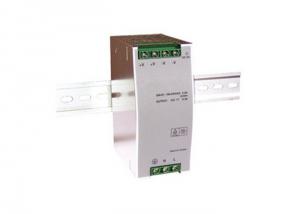
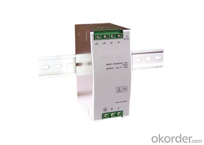
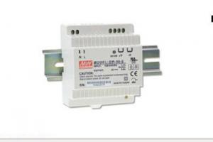
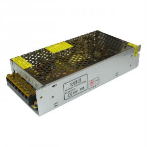
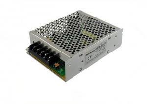
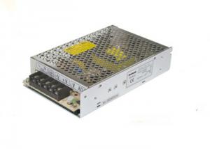
Din Rail Power Supply 50 Watt
- Ref Price:
-

- Loading Port:
- China Main Port
- Payment Terms:
- TT or LC
- Min Order Qty:
- 1 Piece pc
- Supply Capability:
- 200,000 Pieces per Day pc/month
OKorder Service Pledge
OKorder Financial Service
You Might Also Like

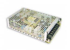

Output Power: 1 - 50W
Output Type: Single
Input Voltage: 85 - 264VAC
Output Voltage: 12 - 48V all available
Output Current: 1 - 4.2A all available
Dimensions: 45 x 89.2 x 75.2mm
Specificatons
All 105C capacitors
Japanese brand for key components
DC OK signal
CE approved
Factory 20 years experience
Features
1) Universal AC input / full range
2) Installed on DIN rail TS35 / 7.5 / 15
3) High reliability, compact design
4) DC OK signal output
5) Protection: overload/ over voltage/ short circuit
6) 100% full load burn-in test
7) Built in EMI filter
8) 5 years limited warranty
9) Dimensions: 45 x 89.2 x 75.2mm
- Q: I have a 12V3A switching power supply. From 0V to 12V, 2V3V can start. Want to carry out voltage regulation. How to do? If you use the potentiometer to connect the kind of potentiometer. I connected to the permanent magnet three brush motor is the car with the wiper motor, the motor high and low speed adjustment. Originally wiper motor there are two blocks. Richer speed adjustment.
- With a potentiometer to the 12V3 amp DC motor speed, the voltage drop in the potentiometer (variable resistor) on the energy consumption of large (and fever), you that 12V3A switching power supply from 0V, 2V, 3V - -12V continuous adjustment
- Q: What is the difference between what we usually call switching power and ups?
- Use is not the same, the function is more different. Not in the same breath.
- Q: We use the switching power supply is 220v-48v, the room has air conditioning, air conditioning power in 6kw or so, the total power of this room in 17kw, DC current is 60A, the room has two tubes. Now do not know how much switching power supply losses, these devices may have 17kw power? This is the 17kw power meter on the show. Who heroes help me.
- The energy meter shows "power", not power. You want to know the actual shaft power of the electrical, the former level is connected to the AC power table, rather than the energy meter. Switching power supply upstairs said it was right.
- Q: Switching power supply start-up time, hold time, long time, fall time, which standard
- Rise time: the output voltage from 10% to 90% of the time, the rise time is generally less than 50ms, too long may cause the machine malfunction. Hold time: After the input power is turned off, the output voltage is maintained with 90% of the specification time.
- Q: What is the difference between an open switching power supply and an ordinary switching power
- Open-type switching power supply generally refers to no sealed shell, and can be cooled by natural air-cooled, all the wind a program to do the power of open switching power supply can do more
- Q: What is the output of this group? If the power supply to the 48V, is not +24 V termination of the electrical 48V + input, -24V termination of the electrical 0? is this okay? Voltage difference is 48V ah? Thank you very much!
- Any voltage is relative to the reference point, +24 V relative to the ground potential difference is 24V, and for -24V is 48V Then -24V to the ground as a reference point is -24V But note that some switching power supply + - output current is different, to check the product manual.
- Q: Now I want to buy a larger power test power, about 1KW. I have no money, so I want to buy a switching power supply, so that you can save a lot of money, but do not know can not accept the emotional load
- If the switching power supply output DC, emotional / capacitive are not afraid. Direct current does not exist.
- Q: Yesterday when the transformer to find a problem, a boost inductance, my air gap plus the greater the inductance of the smaller, but a counterattack transformer my air gap plus the more inductance but the greater, now a bit can not figure out.
- You are not a flyback transformer only done once the air gap concluded that there may be two of your core wrapped around the loose is not the same, anyway, it is impossible under the same conditions, the air gap to increase the amount of inductance but large.
- Q: 12V switching power supply measurement 13.7V normal?
- Adjust it to 12V, the terminal next to the adjustment potentiometer
- Q: Switching power supply, what is the hard switch? What is a soft switch?
- Hard switch is the switch in the inherent cycle, and the soft switch is different, is the use of the role of oscillation in the voltage and current is zero to open and close the switch, which greatly reduces the loss on the switch, The efficiency of the.
1. Manufacturer Overview
| Location | Shanghai,China (Mainland) |
| Year Established | 1995 |
| Annual Output Value | |
| Main Markets | North America 10% South America 3% Eastern Europe 5% Southeast Asia 8% Africa 2% Oceania 2% Mid East 1% Eastern Asia 2% Western Europe 15% Northern Europe 10% Southern Europe 1% South Asia 2% Domestic Market 39% |
| Company Certifications | CE/LVD Certificate; TUV Certificate; Hengfu Logo Registration Certificate; RoHS Certificate |
2. Manufacturer Certificates
| a) Certification Name | |
| Range | |
| Reference | |
| Validity Period |
3. Manufacturer Capability
| a) Trade Capacity | |
| Nearest Port | Shanghai |
| Export Percentage | 31% - 40% |
| No.of Employees in Trade Department | |
| Language Spoken: | English, Chinese |
| b) Factory Information | |
| Factory Size: | 10,000-30,000 square meters |
| No. of Production Lines | Above 10 |
| Contract Manufacturing | Design Service Offered Buyer Label Offered |
| Product Price Range | |
Send your message to us
Din Rail Power Supply 50 Watt
- Ref Price:
-
- Loading Port:
- China Main Port
- Payment Terms:
- TT or LC
- Min Order Qty:
- 1 Piece pc
- Supply Capability:
- 200,000 Pieces per Day pc/month
OKorder Service Pledge
OKorder Financial Service
Similar products

Hot products
Hot Searches
Related keywords

