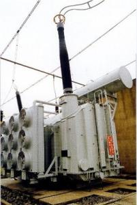
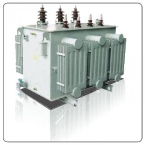
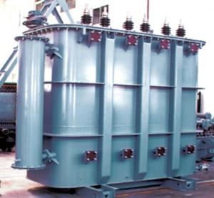
334MVA/500kV single-phase OLTC auto-transformer
- Ref Price:
-

- Loading Port:
- Tianjin
- Payment Terms:
- TT OR LC
- Min Order Qty:
- 1 pc
- Supply Capability:
- 1 pc/month
OKorder Service Pledge
OKorder Financial Service
You Might Also Like


Quick Details
| Place of Origin: | HeBei | Brand Name: | CNBM | Model Number: |
|
| Usage: | Power | Phase: | Three | Coil Structure: | Toroidal |
| Coil Number: | 3 Winding | Capacity: | Rated Voltage: | 334MVA/500kV | |
| Connection Symbol: | YNd11 Dyn11 YNyn0d11 | Tank: | Cover type or Bell type | OLTC: | MR or ABB or SMS |
Packaging & Delivery
| Packaging Detail: | Mainbody --naked Disassembled parts -- crate |
| Delivery Detail: | 3 months |
Specifications
1. CESI certificate
2. High short-circuit withstand
3. Low loss, PD and noise
4. CTQC certificate
5. No leakage
Description
The application of 334MVA/500kV single-phase OLTC auto-transformercan significantly improve the economy of the OLTC substation, and matches well with the transmission capacity of OLTC lines, which has wide prospect of application. Because of its large capacity and large volume, the whole transportation weight with nitrogen is about 470-490 tons, and due to the restricted transport conditions, the transportation becomes the critical issue for application of the334MVA/500kV single-phase OLTC auto-transformer. In order to make the products applicable to any UHV substation in our country, the state grid of corporation of China set the "A study of easy-transport large capacity UHV Transformer” as a key scientific research projects, and entrusted BTW to carry out the research.
During the process of research and development, BTW adopted the advanced design technology and modular design, the transformer can be transported disassembly and with advantages of compact core and winding body, less transportation weight and low transportation cost, effectively solves the need of OLTC construction in the transportation restricted areas. By using the most advanced 3D magnetic field calculation software, BTW performed detailed analysis and calculation for the magnetic flux leakage and eddy current loss of the transformer coil, iron core and oil tank steel structures. Besides, by using of the advanced electric field calculation software, BTW performed detailed analysis and calculation of main longitudinal insulation, and mastered the arrangement of the main longitudinal insulation of large capacity OLTCtransformer and the control of distribution of winding magnetic flux leakage. All of which make the products with low loss, low noise, small volume, strong anti short circuit ability, no local overheating and other significant advantages, and guarantee the long-term safe and stable operation.
The world's first on-site assembled large capacity OLTC Transformer’s right at the first time once again filled the gap in the field of OLTC transformer research after Chinese transformer industry overcame the difficulty of integral transport of 334MVA/500kV single-phase OLTC auto-transformer, which marks BTW has fully occupied the world transformer industry technical peak. The successful development of the product filled the gaps in the domestic technology and met the urgent need of UHV construction application in our country, greatly improved the technical level and manufacturing ability of BTW in terms of OLTC Transformer products.
- Q:What is the reactive power compensation of the transformer?
- The use of capacitors to compensate for reactive power, improve the transformer's active power output capability.
- Q:I am powering a lighting system with a mixture of SCR dimmers and HID lamps. I am pulling approx 285 amps/leg at 120/208V through a 150 kVA transformer. The 120/208V service coming from that transformer is indicated to be 400A/leg, but it seems to get pretty hot at 285A.
- From your readings ,the transformer is within it's rating. Power Transformers are usually rated to operate at 75 Deg. C and above. Sometimes up to 95 Deg. C. The data and limit will be on the nameplate. 75 Deg. C is uncomfortably hot. 95 Deg. C. will burn you. Note; SCR dimmers WILL produce harmonic currents that will increase the 'neutral load' well above 'phase load' on 'common neutral' circuits, and might be producing some high frequency heating in that T/F.
- Q:does anybody know what Transformers 2: Revenge of the Fallen is going to be about? Like what is the whole plot, or storyline?
- The battle for Earth has ended but the battle for the universe has just begun. After returning to Cybertron, Starscream assumes command of the Decepticons, and has decided to return to Earth with force. The Autobots believing that peace was possible finds out that Megatron's dead body has been stolen from the US Military by Skorpinox and revives him using his own spark. Now Megatron is back seeking revenge and with Starscream and more Decepticon reinforcements on the way, the Autobots with reinforcements of their own, may have more to deal with then meets the eye. I'd take that with a pinch of salt though as it's probably fan invented.
- Q:Branch circuit cables are rated for 75?C and feeder cables are rated for90°C. This will be a 3-phase, 575-volt system with four induction motors, specified asfollows:Motor 1: 60 hp 0.90 p.f. squirrel cage motorMotor 2: 60 hp 0.90 p.f. squirrel cage motorMotor 3: 40 hp 0.85 p.f. wound rotor motorMotor 4: 7-1/2 hp 0.80 p.f. wound rotor motorA) Assuming no line losses, find the capacity of the transformer required to supplypower to this system.B) Assume that it is desired to improve the overall power factor for this system to 0.95lagging. Determine, in kVAR, the required capacitance for this power factorcorrection.C) Assume these motors have their windings connected in a delta configuration. Whatwould be the line voltage if they were connected in wye?
- I would look in the NEC for the full load amperes of these motor sizes. These are: 7.5 HP9 amps 40 HP.41 amps 60 HP.62 amps The 7.5 HP motor KVA will be KVA 575 * 9 * 1.732 8.9631 The 7.5 HP motor KW will be KW 575 * 9 * 1.732 * 0.8 7.17048 The KVAR of this motor is Sqrt(8.9631^2 - 7.1705^2) 5.3778 The 40 HP motor KVA will be KVA 575 * 41 * 1.732 40.8319 The 40 HP motor KW will be KW 575 *41 * 1.732 * 0.8 5 34.707115 The KVAR for this motor is Sqrt(40.8319^2 - 34.7071^2) 21.5095 The 60 HP motor KVA will be KVA 575 * 62 * 1.732 61.7458 The 60 HP motor KW will be KW 575 *62 * 1.732 * 0.8 5 55.5712 The KVAR for this motor is Sqrt(61.7458^2 - 55.5712^2) 26.9141 The total KVA requirement for all motors running at once is 8.9631 + 40.8319 + 61.7458 + 61.7458, which is 173.2866 KVA (note this is the requirement from a transformer, not the size of the transformer The total KW of all the motors is 7.1701 + 34.7071 + 55.5712 + 55.5712 153.0196 KW The total KVAR of all the motors is 5.3778 + 21,5095 + 26,9141 + 26.9141 80.7145 KVAR The power factor for all the motor is KW / KVA 153.0196 / 173.2866 0.883 I took a short cut at this point and used an application i wrote to calculate the required capacitor KVAR. The results follows: At 0.95 power factor, the motors' KVA will be 161.065 The motors' KW will be the same. The motors' KVAR will be 50.2926 The required capacitor's KVAR will be 53.988 The reactance of the capacitor will be 10.65 ohms The capacitance will be 3.49059248 E -4 Farads You can calculate these values as I did above, if you want to. EDIT Forgot the last answer. The line voltage is the same for both delta and wye. The leg voltage for the wye motor will be 575 / 1.732 331.98 volts TexMav
- Q:I really want a better transformers than 4 1 was great 2 was crap 3 good 4 worst of them all
- All signs are pointing to yes there will be another one, although it's a long-shot that it will be any better than the other films. The studio and filmmakers have found a formula that puts audiences into theaters, and it likely will be more of the same.
- Q:I can't remember the funny scenes from any the Transformers movies, especially 1 and 2.It's driving me nuts.I saw the third one just last week so I remember a couple of funny scenes, but other than that, no luck.If you can, could you please include a link to a video clip of the scene?Thanks so much! (:
- Here okorder
- Q:Does anyone know where I can buy Transformers in Bluray? I have looked for it everywhere and can't find it and I need it for a Christmas gift.Thanks!
- im not sure but i believe dreamworks to be one of the companies not supporting blu ray
- Q:I have halogen lights in my basement. When i mean contact i am talking about this little hanging jack where by you plug in the light bulb into. For some reason, one of my lights are not working properly but I have already tested the light bulbs out. I have a feeling that the contact/transformer (hanging jack slot) is ineffective. Does anybody have an idea how to change these things?
- Pull a light from one that you know is working and try that, also if your not using sealed bulbs don't touch the lamp. It depends on the type transformer if that is your problem, turn off the power, remove it and order the replacement part
- Q:If I have a primary coil and secondary coil each with 400 turns that acts as a transformer, and the primary potential difference is 2.988 V, and the secondary potential difference is 0.0551 V.I need to find the efficiency. Ideally, it would be 100%, but this is the real world. So I did N(turns) and Volts and used the equation [N(p)V(s)/N(s)V(p) ] *100%p primarys secondaryNturns of coilV potential differenceI had an answer of 1.84% which seems awfully low. Help please. Thanks!
- You are right. The efficiency is that low. Take a look at it another way: Pin Pout if 100% efficient. Since we know a 1:1 turns ratio will produce the same voltage from one side of the transformer to the other, the current produced on the secondary is extremely low to pull the voltage down to .0551V. It makes this transformer extremely inefficient! I can't even think of how you would design a transformer that was this inefficient. I think even a large OD iron nail with a lot of eddy currents at 7.5k Hz I believe would be more efficient. The next worst way I can think of how to produce an isolated output is with a TEC using the Seabeck effect that is about 6% efficient.
- Q:Two different impedance of the transformer, parallel load how to allocate?
- When the impedance voltage is equal, the transformer runs side by side: Because the transformer load distribution is proportional to its rated capacity, and inversely proportional to the impedance voltage. In other words, when the transformer is running in parallel, if the impedance voltage is different, the load is not proportional to the rated capacity of the distribution, parallel transformer current and impedance voltage is inversely proportional to the II / III = UZKII / UZKII or UZKIIII = UZKIIIII, Set two transformers running side by side, the capacity of SNI, SNII, impedance voltage UZI, UZII, then the load of each transformer according to the following formula: SI = [(SNI + SNII) / (SNI / UZKI + SNII / UZKII)] * (SNI / UZKI) SII = [(SNI + SNII) / (SNI / UZKI + SNII / UZKII)] * (SNII / UZKII) That is, S △ I / SII = (SNI * UZKII) / (SNII * UZKI) According to the above analysis we can see: When two transformers with different impedance voltage are running side by side, the distribution load with large impedance voltage is small. When this transformer is full load, another transformer with small impedance voltage will run over load. Transformer long-term overload operation is not allowed, therefore, only the impedance of the transformer voltage overload operation, thus limiting the total output power, energy loss also increased, it can not guarantee the economic operation of the transformer. Therefore, in order to avoid the impedance voltage difference is too large, so that the parallel transformer load current distribution is uneven, affecting the transformer capacity can not be fully played, the specified impedance voltage can not be a difference of 10%.
1. Manufacturer Overview |
|
|---|---|
| Location | |
| Year Established | |
| Annual Output Value | |
| Main Markets | |
| Company Certifications | |
2. Manufacturer Certificates |
|
|---|---|
| a) Certification Name | |
| Range | |
| Reference | |
| Validity Period | |
3. Manufacturer Capability |
|
|---|---|
| a)Trade Capacity | |
| Nearest Port | |
| Export Percentage | |
| No.of Employees in Trade Department | |
| Language Spoken: | |
| b)Factory Information | |
| Factory Size: | |
| No. of Production Lines | |
| Contract Manufacturing | |
| Product Price Range | |
Send your message to us
334MVA/500kV single-phase OLTC auto-transformer
- Ref Price:
-
- Loading Port:
- Tianjin
- Payment Terms:
- TT OR LC
- Min Order Qty:
- 1 pc
- Supply Capability:
- 1 pc/month
OKorder Service Pledge
OKorder Financial Service
Similar products


New products


Hot products


Hot Searches
Related keywords

