
Oil immersed Distribution Transformers 6-10kV
- Ref Price:
-

- Loading Port:
- China Main Port
- Payment Terms:
- TT OR LC
- Min Order Qty:
- -
- Supply Capability:
- -
OKorder Service Pledge
OKorder Financial Service
You Might Also Like


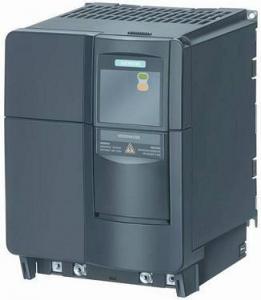


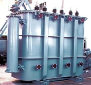
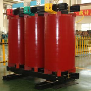
6-10kV Oil-immersed DistributionTransformers

1. Introduction
6-10kV oil-immersed distributiontransformers with capacity 30-3150kVA are suitable for 6-10kV distributionnetwork system. Product complies with GB/T6451-2008 standards.
Type 9, 11 and 13 are classified byloss standard. Two types of oil tank are provided, they are sealed corrugatedradiating and sheet radiator. Voltage can be adjusted with load through switchinstalled.
2. Characteristics
Fully sealed corrugated tank has corrugatedsheet for transformer oil natural cooling. There is no oil storage cabinetneeded, so the oil is completely isolated from air. This design slows down theaging of oil, eliminates maintenance and extends the transformer life.
3. Technical parameters
Technical parameters of S9-Mcorrugated tank transformers
Code | Rated capacity (kVA) | rated voltage(kV) | Loss (xW) | Short Circuit impedance (%) | No Load Current (%) | Connection Symbol | Weight (kg) |
Dimension L*W*H (mm) | mm | |||||
HV | LV | No Load | Load | |||||||||||
Body | Oil | Total | ||||||||||||
S9-M-100 | 100 |
10 6.3 6 | 6.3 6 | 290 | 1500/1580 |
4.0 | 1.8 |
Yyn0 Dyn11 | 285 | 105 | 515 | 800x680x1030 | 550/550 | |
S9-M-125 | 125 | 340 | 1800/1890 | 1.7 | 355 | 110 | 625 | 920x700x1060 | 550/550 | |||||
S9-M-160 | 160 | 400 | 2200/2310 | 1.6 | 420 | 130 | 740 | 970x730x1070 | 550/550 | |||||
S9-M-200 | 200 | 480 | 2600/2730 | 1.5 | 475 | 160 | 825 | 1020x740x1085 | 550/550 | |||||
S9-M-315 | 315 | 670 | 3650/3830 | 1.4 | 710 | 205 | 1200 | 1350x740x1115 | 550/550 | |||||
S9-M-500 | 500 | 960 | 5150/5410 | 1.2 | 925 | 285 | 1575 | 1470x795x1310 | 660/660 | |||||
S9-M-630 | 630 | 1200 | 6200 |
4.5 | 1.1 | 1085 | 320 | 1835 | 1540x830x1360 | 660/660 | ||||
S9-M-800 | 800 | 1400 | 7500 | 1.0 | 1375 | 435 | 2340 | 1630x920x1430 | 820/820 | |||||
S9-M-1000 | 1000 | 1700 | 10300 | 1.0 | 1480 | 485 | 2600 | 1755x1035x1450 | 820/820 | |||||
S9-M-1250 | 1250 | 1950 | 12000 | 0.9 | 1760 | 575 | 3135 | 1870x1120x1540 | 820/820 | |||||
S9-M-1600 | 1600 | 2400 | 14500 | 0.8 | 2125 | 700 | 3795 | 1970x1170x1645 | 820/820 | |||||
Technicalparameters for S11-M corrugated tank transformers
Code | Rated capacity (kVA) | rated voltage(kV) | Loss (xW) | Short Circuit impedance (%) | No Load Current (%) | Connection Symbol | Weight (kg) | Dimension L*W*H (mm) | mm | ||||
HV | LV | No Load | Load |
|
|
| Body | Oil | Total |
|
| ||
S11-M-160/10 | 160 |
10 6.3 6 |
0.4 6.3 6 | 280 | 2200/2310 |
4.0 | 1.6 |
Yyn0 Dyn11 | 490 | 100 | 795 | 1135x713x180 | 550/550 |
S11-M-200/10 | 200 | 340 | 2600/2730 | 1.5 | 540 | 175 | 880 | 1168x738x1200 | 550/550 | ||||
S11-M-250/10 | 250 | 400 | 3050/3200 | 1.4 | 665 | 200 | 1025 | 1240x780x1240 | 550/550 | ||||
S11-M-315/10 | 315 | 480 | 3650/3830 | 1.3 | 730 | 220 | 1155 | 1300x835x1265 | 550/550 | ||||
S11-M-400/10 | 400 | 570 | 4300/4520 | 1.2 | 895 | 300 | 1390 | 1390x905x1310 | 550/550 | ||||
S11-M-500/10 | 500 | 680 | 5150/5410 | 1.1 | 1025 | 360 | 1650 | 1470x965x1365 | 550/550 | ||||
S11-M-630/10 | 630 |
0.4 | 810 | 6200 |
4.5
5.5 | 1.0 | 1650 | 415 | 2260 | 1575x1010x1430 | 660/660 | ||
S11-M-800/10 | 800 | 980 | 7500 | 1.0 | 1510 | 470 | 2550 | 1685x940x1545 | 820/820 | ||||
S11-M-1000/10 | 1000 | 1150 | 10300 | 0.9 |
Dyn11 | 1640 | 650 | 3070 | 2180x1075x1655 | 820/820 | |||
S11-M-1250/10 | 1250 | 1360 | 12800 | 0.8 | 2010 | 820 | 3700 | 2310x1310x1715 | 820/820 | ||||
S11-M-1600/10 | 1600 | 1640 | 14500 | 0.8 | 2420 | 990 | 4470 | 2460x1514x1920 | 820/820 | ||||
S11-M-2000/10 | 2000 | 2240 | 16830 | 0.8 | 2860 | 1120 | 5050 | 2782x1600x2040 | 820/820 | ||||
S11-M-2500/10 | 2500 | 2640 | 19550 | 0.8 | 3195 | 1155 | 5912 | 2500x2060x2010 | 820/820 | ||||
Parameters for 6-10kV SZ11 OLTC Transformers
Code | Rated capacity (kVA) | Rated voltage (kV) |
| Loss(xW) | Short Circuit impedance (%) | No Load Current (%) | Connection Type Symbol | Weight (kg) | Dimension L*W*H(mm) | mm) | ||||
HV | LV | No Load | Load | Body | Oil | Total | ||||||||
S11-M-200/10 | 200 |
10 6.3 6 |
0.4 |
±4x2.5%
| 0.48 | 3.06 |
4.0 | 1.5 |
Yyn0 Dyn11 | 531 | 241 | 1058 | 1510x820x1460 | 550/550 |
S11-M-250/10 | 250 | 0.56 | 3.60 | 1.4 | 630 | 350 | 1400 | 1740x1020x1440 | 550/550 | |||||
S11-M-315/10 | 315 | 0.67 | 4.32 | 1.4 | 860 | 280 | 1630 | 1790x1050x1570 | 550/550 | |||||
S11-M-400/10 | 400 | 0.80 | 5.22 | 1.3 | 910 | 400 | 1740 | 1830x1120x1630 | 660/660 | |||||
S11-M-500/10 | 500 | 0.96 | 5.21 | 1.2 | 1080 | 460 | 2068 | 1900x1230x1780 | 660/660 | |||||
S11-M-630/10 | 630 | 1.20 | 7.65 | 1.1 | 1396 | 611 | 2661 | 2010x1320x1930 | 660/660 | |||||
S11-M-800/10 | 800 | 1.40 | 9.36 | 1.0 | 1650 | 780 | 3220 | 2280x1370x2220 | 820/820 | |||||
S11-M-1000/10 | 1000 | 1.70 | 10.98 | 1.0 | 2083 | 843 | 4240 | 2170x1160x2320 | 820/820 | |||||
S11-M-1250/10 | 1250 | 1.95 | 13.05 | 0.9 | 2390 | 1100 | 4950 | 2510x1310x2630 | 820/820 | |||||
S11-M-1600/10 | 1600 | 2.40 | 15.00 | 0.8 | 2900 | 1065 | 5235 | 2570x1382x2650 | 820/820 | |||||
Note: The above parameter before slash is forYyn0 connection type and after slash is for Dyn11 connection type.
- Q:Design a control circuit to step-up/step-down the voltage either in primary or secondary side of the transformer. The tapping (step-up/step-down) of the transformer must be auto controlled by VB program.For example, suppose if the desire voltage in the secondary of the transformer is 15V, but because of the loss, the voltage might drop to 12V. So, a sensor is used to detect this drop and send the message to VB. VB will process the message and send the reply signal to control circuit so that the voltage will step up (compensated) to 15 V. If the voltage exceeds 15 V, VB has to rectify it also.Can anyone please show me some guidances or circuit diagram of this project? Thank you!!!!
- Thank okorder
- Q:I broke a small transformer that I found inside of my DVD player, and I would like to have one (not for the DVD player, just separately) I would like the transformer to take in low voltage, such as a few AA or AAA batteries, and I want it to scale that up. Does anyone know where I can get one? If not are there any instructions on how to make an effective yet inexpensive one?Thanks in advance!
- A transformer cannot step up or step down DC power. (All batteries are DC). That is part of their nature. A basic transformer is nothing more than two (or more) inductor coils in close proximity, often with a steel core to help with the magnetic fields. All inductor coils are basically a coil of conducting wire, most often copper.
- Q:Transformer and the middle of what is the difference
- Often referred to as the transformer is the frequency transformer, is used to change the size of the AC voltage electrical equipment. It is based on the principle of electromagnetic induction, with the same frequency, between two or more windings, the exchange of AC voltage and current to transmit electrical energy of the static electrical equipment.
- Q:design a quarter wave transformer to match a 73 ohms antenna to 300 ohms transmission line fed by a 100MHz FM radio station
- Transformer impedance required: sqrt (73 x 300) 147.986 (say 148) ohms. The 1/4 wavelength in air is (75/100) 0.75 metres. You have not stated what you are using for the transformer, so you will need to allow for its velocity factor. But the transformer could be 0.75 metres of parallel rod spaced as required for the impedance. I am also assuming the antenna is balanced (sounds like a folded dipole).
- Q:What is the meaning of the high voltage side and the low side of the transformer?
- In general, the "high voltage side" refers to the "side of the high voltage side" (high pressure side) "low side" from the power supply to the primary side of the transformer (low voltage outlet) The From the wiring is also basically able to distinguish: high side (into the end) is generally "△" connection, low side (outlet) is generally "Y" connection.
- Q:Hi, I need a High Frequency( example~200khz) High voltage(200 000v) power supply at low microcurrent, I know that a Tesla coil fits the bill very easily . But I need to manually VARY the frequency(say from 100khz to 200khz ) while keeping the High voltage the same? Is this possible, Can some one guide me where I can buy or build this? Can I just for instance connect just a van de graaf or a rectified Tesla Coil to a function generator? If not what do I need to do to achieve what I want? I have been searching without help so your support is much appreciatedThanks
- The Tesla coil needs to operate at the same resonant frequency on both the primary and secondary sides of the loosely coupled transformer. The resonant frequency is set by the inductance and capacitance of each side. The problem is there are no high voltage solid state capacitors (varactor diodes like you see in r.f. receivers that adjust the tank circuit frequency) on the primary side, and no way to adjust the top hat toroid capacitor on the secondary side (unless maybe it was a mylar covered balloon with vacuum deposited aluminum that could be remotely inflated or deflated). So you are stuck with whatever high voltage capacitor and toroid top hat you have on hand, and the inductance of the coils you wind that ends up being the resonant frequency. Even then it takes a lot of fiddling to get both in tune to give the maximum voltage output. The input frequency to the primary coil (the 555 circuit used in the step up with the flyback transformer- its frequency was chosen solely due to the flyback's frequency design) has little to do with the primary's resonant frequency; again that is set by the capacitor used and the size and number of turns of the primary coil.
- Q:HELP!! My boyfriend wants to see transformers and he told me I had to study up first lol! He wants me to know who all of the characters are because apparantly its from a comic or cartoon or something? I dunno but can anyone tell me anything about the TRANSFORMERS? I need to know characters and storyline etc. basically just anything u knowThanks lol.
- well, transformers is basically about two groups of opposing robots in a war againts each other. one good, the other bad. they live in a planet called cybertron and apparently, their planet is on the verge of dying because of the said war. their way of actually saving their planet is to search for a cube or something (i'm not entirely sure where the cubes come from) which they can use to revive their planet or take over another planet and make it their own. a cube is detected to be on earth and so they come here to get it and hence the story you should watch the movie, i've already seen it and it was really really great
- Q:a house's two furnaces are not working. the pilot lights are on. The lady's brother said there is no voltage at the thermostat. where does the 24 v come from? a transformer ? where?
- there will be no Reference to the 24 volt ground at the thermostat so checking for voltage there is a bad idea. some ware in the control circuit there is a transformer. the pilot light does not require 24 volt to remain on. look at the schematics on the inside of the access door to help you locate the 24 volt source. on an older furnace you do not need any voltage to light your pilot light. you could have a bad fuse
- Q:What is the meaning of the Y D11 on the transformer?
- Transformer Y / D11 Y ----- primary side connection, star type, D secondary side connection, triangle 11 is the primary and secondary side of the phase difference of the side line voltage lag secondary side 330 degrees (or lead 30 degrees).
- Q:I have a standard transformer with 7 wires:2 black2 red2 yellow1 red/yellow stripedWhat connections do these wires correspond to?That is, which should connect internally to the primary coil, the secondary coil, and coil-taps (based on the number of wires, I assume that the secondary coil is tapped).I must determine this in order to connect the wires (externally) appropriately.Any help is greatly appreciated!
- Pin Number Wire Color Function 1 Not Used Not Used 2 Black Ground 3 Grey Right Positive 4 Grey/Black Right Negative 5 Blue/White Amplifier Remote 6 Red 12 Volt Switched 7 Yellow 12 Volt Constant 8 White Left Positive 9 White/Black Left Negative
1. Manufacturer Overview |
|
|---|---|
| Location | |
| Year Established | |
| Annual Output Value | |
| Main Markets | |
| Company Certifications | |
2. Manufacturer Certificates |
|
|---|---|
| a) Certification Name | |
| Range | |
| Reference | |
| Validity Period | |
3. Manufacturer Capability |
|
|---|---|
| a)Trade Capacity | |
| Nearest Port | |
| Export Percentage | |
| No.of Employees in Trade Department | |
| Language Spoken: | |
| b)Factory Information | |
| Factory Size: | |
| No. of Production Lines | |
| Contract Manufacturing | |
| Product Price Range | |
Send your message to us
Oil immersed Distribution Transformers 6-10kV
- Ref Price:
-
- Loading Port:
- China Main Port
- Payment Terms:
- TT OR LC
- Min Order Qty:
- -
- Supply Capability:
- -
OKorder Service Pledge
OKorder Financial Service
Similar products


New products
Hot products


Hot Searches
Related keywords

