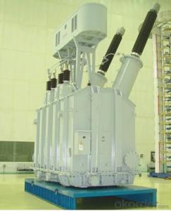
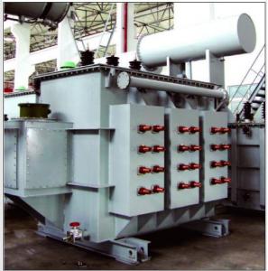
31.5MVA/220kV single phase traction transformer
- Ref Price:
-

- Loading Port:
- Tianjin
- Payment Terms:
- TT OR LC
- Min Order Qty:
- 1 pc
- Supply Capability:
- 1 pc/month
OKorder Service Pledge
OKorder Financial Service
You Might Also Like


Quick Details
| Place of Origin: | HeBei | Brand Name: | CNBM | Model Number: |
|
| Usage: | Power | Phase: | Three | Coil Structure: | Toroidal |
| Coil Number: | 3 Winding | Capacity: | Rated Voltage: | 31.5MVA/220kV | |
| Connection Symbol: | YNd11 Dyn11 YNyn0d11 | Tank: | Cover type or Bell type | OLTC: | MR or ABB or SMS |
Packaging & Delivery
| Packaging Detail: | Mainbody --naked Disassembled parts -- crate |
| Delivery Detail: | 3 months |
Specifications
1. CESI certificate
2. High short-circuit withstand
3. Low loss, PD and noise
4. CTQC certificate
5. No leakage
Description
The application of the 31.5MVA/220kV single phase traction transformer, and matches well with the transmission capacity of UHV lines, which has wide prospect of application. Because of its large capacity and large volume, the whole transportation weight with nitrogen is about 470-490 tons, and due to the restricted transport conditions, the transportation becomes the critical issue for application of the 31.5MVA/220kV single phase traction transformer. In order to make the products applicable to any UHV substation in our country, the state grid of corporation of China set the "A study of easy-transport large capacity UHV Transformer” as a key scientific research projects, and entrusted BTW to carry out the research.
During the process of research and development, BTW adopted the advanced design technology and modular design, the transformer can be transported disassembly and with advantages of compact core and winding body, less transportation weight and low transportation cost, effectively solves the need of UHV construction in the transportation restricted areas. By using the most advanced 3D magnetic field calculation software, BTW performed detailed analysis and calculation for the magnetic flux leakage and eddy current loss of the transformer coil, iron core and oil tank steel structures. Besides, by using of the advanced electric field calculation software, BTW performed detailed analysis and calculation of main longitudinal insulation, and mastered the arrangement of the main longitudinal insulation of large capacity UHV transformer and the control of distribution of winding magnetic flux leakage. All of which make the products with low loss, low noise, small volume, strong anti short circuit ability, no local overheating and other significant advantages, and guarantee the long-term safe and stable operation.
The world's first on-site assembled large capacity UHV Transformer’s right at the first time once again filled the gap in the field of UHV transformer research after Chinese transformer industry overcame the difficulty of integral transport of the 31.5MVA/220kV single phase traction transformer, which marks BTW has fully occupied the world transformer industry technical peak. The successful development of the product filled the gaps in the domestic technology and met the urgent need of UHV construction application in our country, greatly improved the technical level and manufacturing ability of BTW in terms of UHV Transformer products.
- Q:An AC generator, originally designed to provide a peak output voltage of ± 155 V at a frequency of 60 Hz, is required to provide a peak output of ± 340 V at 50 Hz. If the generator is connected to a transformer with 200 loops in its primary coil, how many loops should there be in the secondary coil in order to provide the required output?Using the formula Np/VpNs/Vs I get 439 coils, but this is too easy for a 6 mark question and doesn't include the change of frequency. I have no idea what to do and need some help :(
- A transformer cannot change frequency. You can change the voltage from 155 v peak to 340 volts peak, but you cannot change the frequency. But you can change the speed of the generator and therefore change the frequency, but I don't know if that is part of the question. usually, I find that if you list the entire question with all the details, then it probably could be answered. But only part of the question will lead to incorrect answers. .
- Q:How to tune to 14V? Why I tune the value of the above voltage meter has been always beating.
- Transformer parameter setting method is: 1, the calculation: According to the ideal transformer primary turns ratio ratio n1 / n2 = V1 / V2 = 220/14 ≈ 15.7, ???????????? Let the primary winding sense L1 = 1H, then the secondary winding inductance L2 = 1 / (15.7 ^ 2) ≈ 0.00406H,
- Q:I want to multiply current 10times for a second or two. So, is there any easy way to do that without using a high power transformer?Thanx.!
- If your output is 8V ac, then a transformer is unfortunately your best bet. You can get real fancy and do a switching power converter/inverter (sort of like the inverters that convert 12V dc in vehicles to 120V ac), but that solution is outside the ability of most designers. You would lose a lot of hair and if you're lucky, it MIGHT be cheaper. ************************************** I'm assuming you want to conserve power and increase I by a factor of 10 while decreasing V by a factor of 10? Remember; P V*I A switching regulator will allow you to transform power from one form to another very efficiently (often 90% or better). It uses an inductor switched cleverly between the source and load. This is used in most modern power supplies instead of a transformer (like laptop supplies, cell phone chargers etc.) Your question is a little vague you can increase current 10 times by reducing the load impedance (resistance) by a facto of 10. Ohms law VI*R or IV/R. Reduce R by 10, increase I by a factor of 10. Hope this helps, Dave
- Q:I know that both at some point were comics made by Marvel and that Thundercats was animated by a japanese studio and Transformers had an original series in japan but was here in america first. That's the info I have but what is what? And please no guessing if you don't know please don't play favorites between american and japanese cartoons, ok?
- Transformers was animated by an American company whom employed Japanese animators, Thundercats was made by Toei who is a Anime company but it was made for Americans.
- Q:I have been reading wikipedia and have gotten confused.Va.Number of Coils on side a---- ._________________Vb.Number of Coils on side bwikipedia mentioned how power companys use transformers for converting to high voltage power li nes then use transformers to bring the voltage back down.Focusing on the transformer that jacks the voltage upwirea-[side a-Transformerxyz- side b]-wirebso assum wireb is the high voltage power line.--Which side of transformerxyz would have more coils ? My guess is that side b has more coils then side a--Is it safe to say that the wattage of side a is equal to side b?--they said something about magnetic flux, does this just mean that the material connecting side a to side b has to be magnetic?--they said that the insulation wears down in transformers over time due to heat. what is causing this heat?--they said something about leakage and spacing of coils, what does this mean?tyVVVVVVVm
- The previous answer is correct, but the following may be helpful. A transformer works by the linking of changing magnetic flux produced by one loop or coil (the primary winding) with another coil (the secondary). That is why transformers only work with alternating current or pulses. Magnetic iron has the ability to increase the magnetic flux produced by a coil. This is called its magnetic permeability and can increase the flux produced by factors of several thousand or more. Leakage flux in a real transformer is the amount of flux produced by the primary that does not link the secondary. This flux is wasted and reduces the efficiency of the transformer. Heating of the wire insulaltion not only comes from the resistive heat of the windings, but also the heat produced in the magnetic material (core) of the transformer. These losses are called eddy current and hysteresis losses and can be quite substantial. The reason that cores of transformers are laminated (stacked thin sheets of magnetic iron) is to reduce the eddy current losses.
- Q:i think transformers
- Simpsons for sure:]
- Q:How to use the experimental method to determine the transformer iron consumption and copper consumption
- No-load test for iron loss; short-circuit test copper loss. I suggest you read the book, see the information.
- Q:a lamp is connected to a secondary coil ( 80 turns) of a transformer by long leads which have a resistance of 2.5 ohms. Primary coil( 1600 turns voltage is 220v). the power input to the primary coil is 44w. 1) what is the voltage across the secondary coil2) what is the current across the secondary coil3) what is the electrical power dissipated in the lamp
- Assuming perfect transformer. turns ratio 1600/80 20:1 secondary voltage is 220/20 11 volts primary current is 44/220 0.2 amps secondary current is 0.2 x 20 4 amps drop across wires is 4 x 2.5 10 volts. This assumes the 2.5 ohm number is for both leads, not each. voltage across lamp is 11v – 10v 1 volt power in lamp is 1 v x 4 a 4 watts. .
- Q:What is the unit of the transformer?
- Transformer (Transformer) is the use of electromagnetic induction principle to change the AC voltage of the device, the main components are primary coil, secondary coil and core (core). The main functions are: voltage conversion, current conversion, impedance conversion, isolation, voltage regulator (magnetic saturation transformer) and so on. According to the purpose can be divided into: power transformers and special transformers (electric furnace change, rectifier, frequency test transformer, voltage regulator, mine transformer, audio transformers, IF transformers, high-frequency transformers, impact transformers, instrument transformers, electronic transformers , Reactors, transformers, etc.). Circuit symbols commonly used as the beginning of the number. Example: T01, T201 and so on.
- Q:Why can autotransformers be used as safety transformers? Isolation transformer is a variable ratio of 1 transformer, why has a security role?
- The high and low voltage side of the autotransformer is realized by tapping in a coil, and there is no magnetic connection between the two times and there is an electrical connection, so it can not be used as a safety transformer. Isolation transformer high and low voltage coil is separated, the only magnetic connection between the two there is no electrical contact, so the role of security protection.
1. Manufacturer Overview |
|
|---|---|
| Location | |
| Year Established | |
| Annual Output Value | |
| Main Markets | |
| Company Certifications | |
2. Manufacturer Certificates |
|
|---|---|
| a) Certification Name | |
| Range | |
| Reference | |
| Validity Period | |
3. Manufacturer Capability |
|
|---|---|
| a)Trade Capacity | |
| Nearest Port | |
| Export Percentage | |
| No.of Employees in Trade Department | |
| Language Spoken: | |
| b)Factory Information | |
| Factory Size: | |
| No. of Production Lines | |
| Contract Manufacturing | |
| Product Price Range | |
Send your message to us
31.5MVA/220kV single phase traction transformer
- Ref Price:
-
- Loading Port:
- Tianjin
- Payment Terms:
- TT OR LC
- Min Order Qty:
- 1 pc
- Supply Capability:
- 1 pc/month
OKorder Service Pledge
OKorder Financial Service
Similar products


New products
Hot products

Hot Searches
Related keywords

