


thermal overload protection relays JZC1-71.80 thermal relays magnetic overload relay overload relay
- Ref Price:
-

- Loading Port:
- Ningbo
- Payment Terms:
- TT OR LC
- Min Order Qty:
- 100 pc
- Supply Capability:
- 5000 pc/month
OKorder Service Pledge
OKorder Financial Service
You Might Also Like

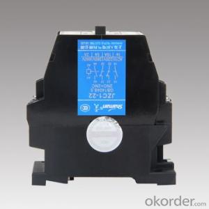
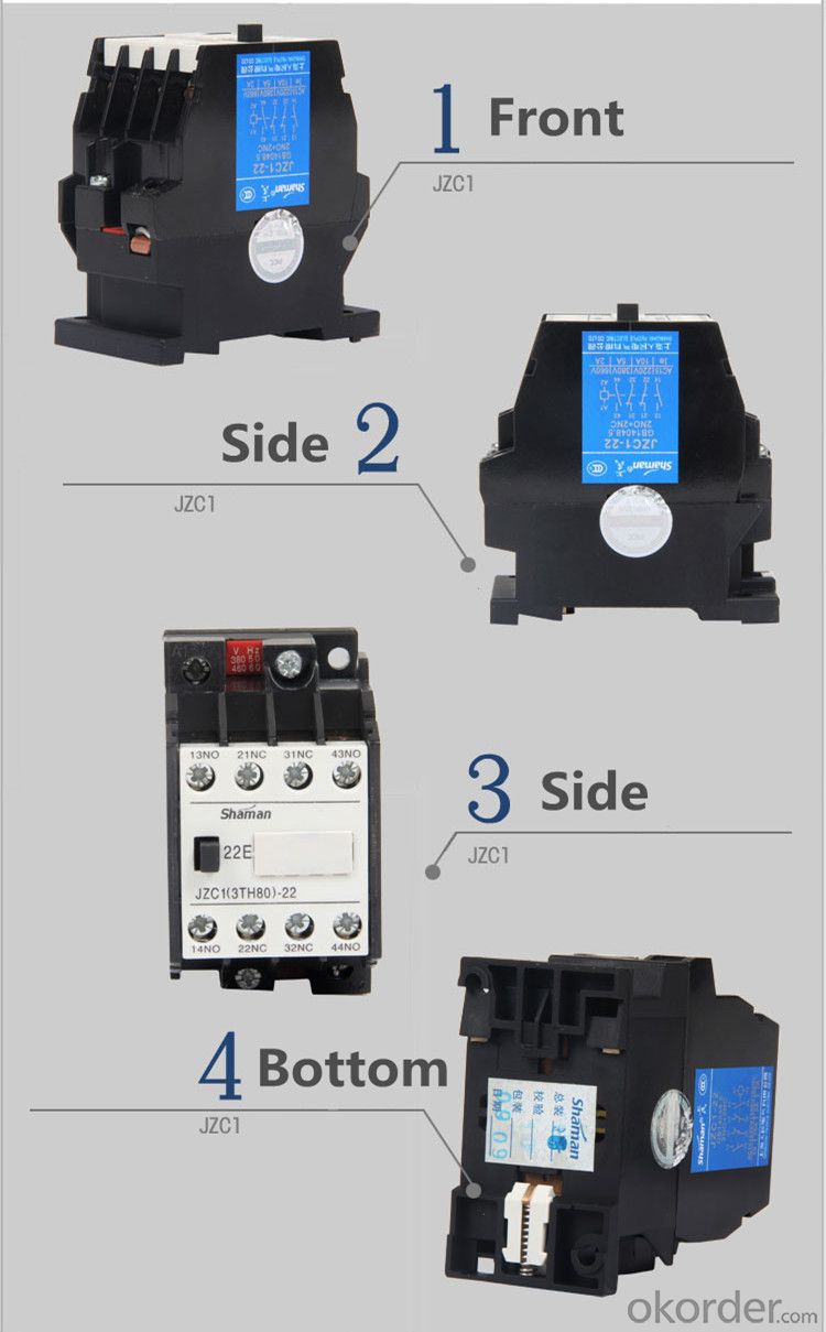
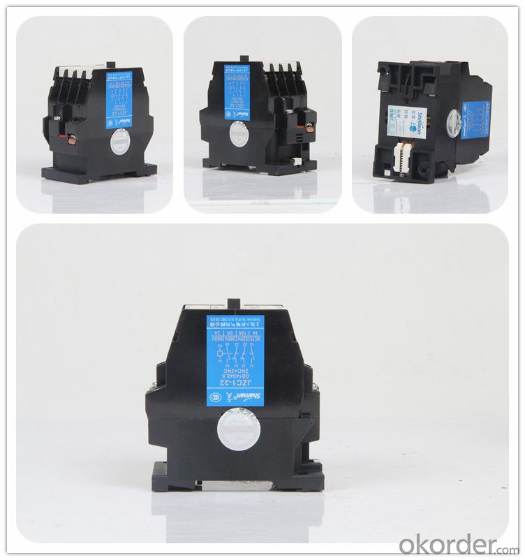
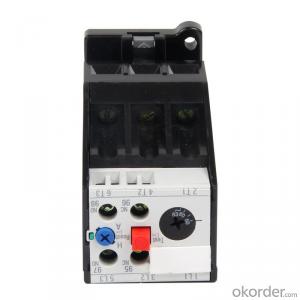
JZC1-71.80 Thermal Relay
Product Details | |||
Brand Name | Shaman | Item No. | JZC1-71.80(3TH82-71.80) |
Color | Black | MOQ | 100 pcs |
Packing | 40 PCS in one carton. | ||
Important Information | |||
Send sample | Yes | ||
Delivery time | Within 30 days. | ||
Payment terms | T/T 30% deposit, the balance before the shipment. | ||
Introduction:
JZC1 contactor type relay for AC 50Hz or 60Hz, rated voltage up to 660V or 600V DC,
rated voltage control circuit to control a variety of electromagnetic coils, so the signal is
sent simultaneously to expand or to signal to the control components.
Specifications:
The technical parameter of JZC1 series Contactor type Relay as follows:
Place of Origin: Zhejiang China(Mainland) | Brand Name: Shaman | Model Number: JZC1 |
Rated frequency: 50Hz | Rated operational voltage: Up to 660V | Rated current(Ie):AC-15: 5DC-13:0.25 |
Description | AC 50Hz, rated voltage up to 660V, rated insulating voltage up to 690V |
Control various kinds of magnetic coils, amplify the signals, electric interlocking or transmit the signals to the controlled element | |
Long-distance connecting and breaking circuit, for frequency start,stop and control small capacity ACmotor | |
Certificate | CCC, RoHS certificates |
Standard | IEC 60947-5-1/GB14048.5 |
Technical data | Auxiliary contact: 4sets,8sets |
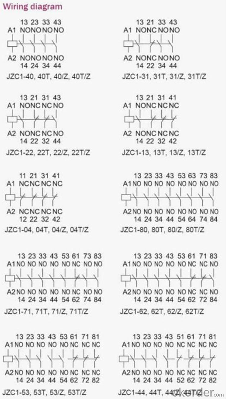
Auxiliary structure: single ply double ply Auxiliary combination: NO NC NO NC 1 3 4 4 2 2 5 3 3 1 6 2 4 0 7 1 0 4 8 0 | |
Operating frequency: 3600time/h | |
Electric life: 1*106 Mechanical life: 10*106 | |
Coil voltage: AC 12~660V DC 12~250V | |
Coil pull-in voltage:80%~110%Us Coil release voltage:20%~75%Us(AC),10%~75%Us(DC) | |
Weight(kg): 0.5(AC single ply) 0.44(AC double ply) 0.7(DC single ply) 0.69(DC double ply) | |
Features | Direct-action structure of Double breaking points |
Sealed auxiliary system structure | |
Terminal with protective covering | |
Also can Handle check | |
Fixed mode: Screw-up and 35mm TH Rail mounting |
Using sort | AC-15 | DC-13 | ||||
Rated working voltage V | 220 | 380 | 660 | 110 | 220 | 600 |
Rated working current A | 10 | 6 | 2 | 0.9 | 0.45 | 0.2 |
Working conditions:
1.The ambient air temperature:
a).The ambient air temperature is up to 40 °c Celsius.
b).The average does not exceed 35 °c Celsius within 24 hours.
2.The ambient air temperature is below to -5 °c Celsius.
3.The altitude of the installation sites do not exceed 2000m.
4.The pollution degree of installation sites is level 3.
5.Installation category is class II.
6.The tilt with the vertical is not more than 5 °c.
7.No space of significant shake and shock and vibration
Control circuit:
The standard value of the rated control power supply and voltage (Us):
AC (50Hz)36V,48V,110V,220V,380V
(60Hz)42V,58V,132V,264V,460V
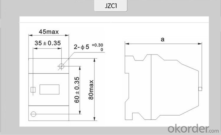
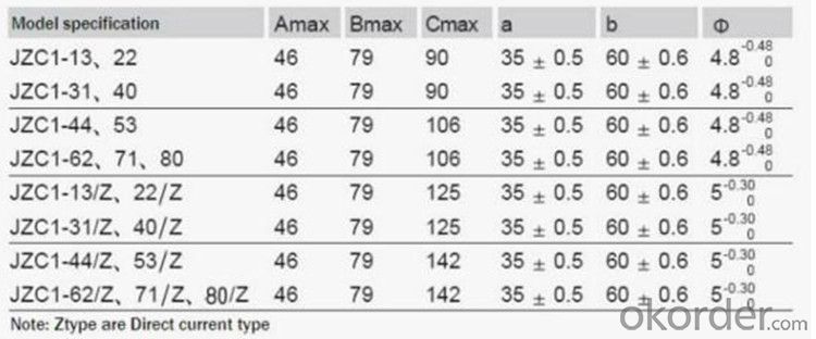
Overall and installation dimension(mm):


- Q:Why the relay coil at both ends to parallel a diode
- At this time, as long as we connect the diode at both ends of the coil, it can make it produce a loop (power equivalent to the end of the coil at both ends of the short line), so that the energy stored in the coil finished. This diode acts as a freewheel here, and we usually call it a freewheeling diode. (Attached: the voltage at both ends of the capacitor can not be sudden changes in the current at both ends of the inductor)
- Q:How the synchronous relays work
- The synchronous relay is used in the automatic reclosing line of the two-terminal power supply system as a checkout element with or without voltage and the same period. The synchronous relay consists of voltage (flow) transformers T1, T2 rectifier filter circuit, voltage comparison circuit and outlet circuit and other components, installed in the combination of plug-in shell.
- Q:Human body infrared sensor module to connect the electrical method
- First determine your 3v relay coil operating current is how much, if not found, you can use a regulated power supply to 3V string into the multimeter (current) access to the relay to pull, write down the current value, if it is 0.1 A, as the downstairs hby8401 said, we have to calculate the current limiting resistor = (9-3) /0.1 = 60 ohms, its power 0.1 * 6 = 0.6W, select at least 1W above 60 ohm resistance access board 1 foot To the top of the relay (diode negative in the figure), and the transistor emitter connected to 3. The base of the limited current resistance directly into the 2 feet bar.
- Q:Static relay and we usually encounter the relay in the structure, function and use of the way there are those differences? What is his advantage?
- The use of the two different principles of subtle differences. Static intermediate relays are used in a variety of protection and automatic control circuits. Such relays by the electronic components and precision small relays, etc., is the power series of intermediate relays replacement products of choice. Static relay without contact, no electromagnetic coil, also known as solid state relay.
- Q:His coil has several joints, two or three, is it its auxiliary contact in series in the control loop
- The key is to see what kind of voltage relay you need, in addition to the coil, there are voltage sampling contacts and output contacts.
- Q:Dc24v power supply one, 6-36v300ma NPN close close proximity switch one, HH52P DC24V intermediate relay one, 24v solenoid valve 120ma one, I was the relay connected into a self-locking line and then drive the solenoid valve work, so close to the switch close to the metal The object to the relay power, solenoid valve homing, before engaged in once, this time from the Internet to buy two (6-36v300ma NPN normally close close switch) how can not drive the depressed relay went to the last time to close the switch Of the physical store to buy a back on the easy to use, more depressed, and two close to the switch contrast, only the load 200MA and 300MA difference, according to the reason that the load 300MA should be better than two hundred ah, so Rookie to ask the Supreme, is the 300mas close to the switch itself or because the load current caused by?
- It is your online to buy a close switch problems. In general, the 200MA current drives the HH52 relay is completely without problems. You buy the relay leakage current is too large, so can not turn off.
- Q:How does the time relay delay the opening action?
- Time relay delay off the moving contact is: when the relay is energized, the movable contact immediately closed; when the relay is powered off, the moving contact is delayed. There are delay off the dynamic contact: relay power, the dynamic contact immediately disconnect; when the relay power, the dynamic contact contact delay. This answer is right! The The The The The The The The The Above the brother who is obviously Baidu paste, answer the question and answer, actually the best answer ~ silent ~
- Q:See the Omron relay (G6K-2F-Y) manual on the "non-latching" (non-latch) and "terminal spacing" these two terms, do not know what the meaning, please enlighten me, the best point
- The latch-type relay actually refers to the "self-locking", that is, after the relay is energized, the state is automatically locked, even if the control current is turned off at this time. In other words, when the power-on, the open control current will continue to keep the pull state, unless the release button, of course, some of the reverse current through the unlock. Ordinary relays, are "monostable", and this relay is "bistable" type.
- Q:How to look at the relay model HH54P What is the type of relay? 3A 240VAC 3A28VDC What does this mean?
- 3A 240VAC refers to the rated load that the contacts can carry. 3A28VDC refers to the rated load that the contact can bring. HH54P Model Meaning: HH means: control relay 5 said: design serial number 4 means: 4 conversion (4 normally open normally closed) P said: plug-in HH54P pin: 14, 13, coil. (Note: DC coil: 14 (+), 13 (-)) 9, 10, 11, 12, respectively, for the four groups of contacts common. 9 --- 5, 10 --- 6, 11 --- 7, 12 --- 8, respectively, for the four groups of normally open contacts. 9 --- 1, 10 --- 2,11 --- 3, 12 --- 4, respectively, for the four groups of normally closed contacts.
- Q:Car electrical appliances are generally switches to the fuse and then to the relay and then to the electrical What about it? It is best to have a clear line map, thanks!
- General is the switch control relay, the relay to the electrical power transmission, that is, the fuse is the relay line of fire. There are individual insurance tube relay outlet. Want you to say that the switch is down insurance, it should be installed with electrical appliances should be a line or a relay. my thoughts.
1. Manufacturer Overview |
|
|---|---|
| Location | |
| Year Established | |
| Annual Output Value | |
| Main Markets | |
| Company Certifications | |
2. Manufacturer Certificates |
|
|---|---|
| a) Certification Name | |
| Range | |
| Reference | |
| Validity Period | |
3. Manufacturer Capability |
|
|---|---|
| a)Trade Capacity | |
| Nearest Port | |
| Export Percentage | |
| No.of Employees in Trade Department | |
| Language Spoken: | |
| b)Factory Information | |
| Factory Size: | |
| No. of Production Lines | |
| Contract Manufacturing | |
| Product Price Range | |
Send your message to us
thermal overload protection relays JZC1-71.80 thermal relays magnetic overload relay overload relay
- Ref Price:
-
- Loading Port:
- Ningbo
- Payment Terms:
- TT OR LC
- Min Order Qty:
- 100 pc
- Supply Capability:
- 5000 pc/month
OKorder Service Pledge
OKorder Financial Service
Similar products


New products


Hot products
Hot Searches

