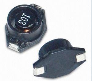
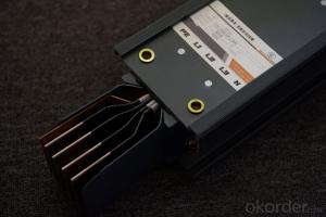
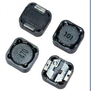
PBP Series Shielded SMD Power Inductor
- Ref Price:
-

- Loading Port:
- China Main Port
- Payment Terms:
- TT or LC
- Min Order Qty:
- 1000 Pieces pc
- Supply Capability:
- 20,000 Pieces per Day pc/month
OKorder Service Pledge
Quality Product, Order Online Tracking, Timely Delivery
OKorder Financial Service
Credit Rating, Credit Services, Credit Purchasing
You Might Also Like
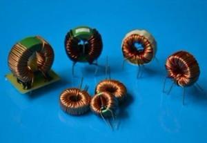
1. pbp series shielded smd power Inductor
2. Rated current:0.5-10A
3. Inductance0.5~6000uH
4. Quality assured
5. competitive price
smallest possible size and high performance they are with high energy storage
Feartures:
The Surface Mount Inductors are designed for the smallest possible size and high performance,
They are with high energy storage and very low resistance making them the ideal inductors for
DC-DC conversion in the following application.
- Q:how do u calculate the SRF of a inductor,for example i have a 90Mhz oscillator,but i need a RF choke to block the RF from entering the other part of the circuit,so the SRF of the RF choke should be more than 90Mhz may be 110Mhz.,so how can i calculate the SRF,i make inductors by myself.so please help me out.
- I was in The Corps right as Vietnam was ending and the rule against laying hands on recruits was not yet in place. It is nothing like it was but I've heard from some more recent marines that things still happen but nothing like it used to be. I saw a guy get spin kicked when standing at attention in the barracks by a DI who was some kind of a kung fu badass and saw a number of recruits get punched. I personally got punched in the gut pretty hard. I also saw a guy get led around by a string tied around his dick on the parade field with his pants around his ankles for screwing up a marching formation. FYI my platoon also had a guy jump from our 3rd story barracks down to the hard deckwe never heard if he lived or died, nothing was ever told to us and the DI's just went ahead with training like nothing had happened. Parris Island was not for the faint of heart back then.
- Q:I am wanting to build an inductor to certain specs.The inductor will operate in the audo frequencies of about 5-20kHz and be wound on an iron core. I need an inductance of about 150mH.How do I determine what type of core I need, what wire size, and the number or turns of wire will be required to make the inductor?Any help or references will be appreciated!
- L u0 ur N^2 A/length Where L is the Inductance and u0 4pi x 10^-7 and ur is the relative permeability of the core material (which should stay constant with current fluctuations) and N is the number of turns and A is the cross sectional area of the core and l is the magnetic path length. . all in SI units. The wire size will depend of how much current the winding has to tolerate without getting too warm. DON'T DO IT! There are so many factors that you'll wish you had never tried. Buy the inductor you need from an electronics shop and make sure its power rating can cope. Don't use an iron core - it will not be able to cope with the higher audio frequencies. A powdered-iron toroid might be best
- Q:A constant voltage of 5.00 V has been observed over a certain time interval across a 1.10 H inductor. The current through the inductor, measured as 2.00 A at the beginning of the time interval, was observed to increase at a constant rate to a value of 6.00 A at the end of the time interval. How long was this time interval?
- Jag tycker det ?r lustigt hur du ska ?vers?tta detta f?r att se vad jag skrev. L?ser du fortfarande h?r? Du borde sluta nu.
- Q:I have a few handfuls of scavenged inductors that I really want to know the inductance of. Some of the air-core inductors I've been able to somewhat successfully (worked in filters I made with them and etc) ballpark the value using formulas and programs from electronics sites. However, that really only works with the ones I am able to figure out the wire gauge and from there the number of layers, and the inner/outer circumference of the core. Also, I have a fair number of ferrous-core inductors that I can't measure either. I don't have the money or resources currently for an oscilloscope or signal generator, although I suppose I could just put together a quick oscillator for a signal to useanyway, isn't it possible to just measure the current through the inductor (or maybe with a known value capacitor too) with 60-hertz line frequency with a known (obviously lower than line) voltage? Then calculate the combined reactance/impedance etc?
- The resistor is used to sense the current.
- Q:Can a capacitor discharge itself through an ideal inductor ? If yes state the reason , if No how will the charge on the capacitor will behave ?
- A charged perfect capacitor connected to a perfect inductor will have an oscillating voltage: discharge to 0, recharge to initial charge value with opposite polarity, back to 0, etc. forever. This is a sinusoidal oscillation which takes place at a frequency 1/sqrt(LC) rad/s. The reason for the oscillation is explained in the ref., which discusses such a circuit with added resistance. The resistance absorbs energy and causes the oscillation to damp out over time, but the behavior of the capacitor and inductor are the same without resistance.
- Q:A 25.0-mH inductor, a 2.00-μF capacitor, and a certain resistor are connected in series across an ac voltage source at 1000 Hz. If the impedance of this circuit is 200 Ω, what is the value of the resistor? a. 200 Ω b. 552 Ω c. 184 Ω d. 100 Ω e. 579 Ω
- C. 184 ohms.
- Q:A certain circuit consists of an inductor of 55 mH in series with a resistor of 90 Ω. At a moment when the current in the circuit is 21 A, a switch in the circuit is opened. How long will it take for the current to fall to 7.14 A? Answer in units of s.I thought that this one was easy. first time around I used i(Io)(e^-Rt/L) --- 7.1421e^(-90t/(55x10^-3)) 2.53926105e-4this is wrong. Then based on someone's advise I got on here, I used the equation i(Io)e^(t/-RL) and I got an answer of 5.34.also wrong! Please help! What am I doing wrong? What's the answer??
- 7.14 21 e^ - (R/L)t e^-(90/0.055) t 0.34 e^- (1636.36 t) 0.34 ln both sides : - 1636.36 t - 1.0788 hence t 6.59 x 10^-4 s
- Q:An inductor that has a resistance of 80 k-Ohms is connected to an ideal battery of 84V. 0.8 milliseconds after the switch is thrown the current in the circuit is .5355mA. Calculate the inductance. Answer in Units of H.I've been having a serious problem with this question. I figured out that there's a voltage drop (the voltage drops to 42.84V). But i'm not entirely sure where to go from there (or if that's even right!). Any help is greatly appreciated as this is an important question that'll be on my final exam.Thanks.
- after the switch is thrown ???? what is this language? is it switched on or off R-L circuitswitched on equation of emf isRI + L dI/dt E LdI/dt [E - RI] LdI/dt R [(E/R) - I] dI /[(E/R) - I] [R/L] dt its solution is [at t0, I 0 (switched on) I (E/R)[1 - exp(- R*t/L)] ------------------- (1) this is how currentgrows in LR circuit R 80000 ohm, E 84 V, t 0.8*10^-3 sec, I 0.5355*10^-3 A 0.5355*10^-3 [84/80000][1 - exp(- 80000*0.8*10^-3/L)] 0.51 [1 - exp(- 64/L)] exp(- 64/L) 1 - 0.51 0.49 flipexp(64/L) 1/0.49 2.041 taking natural log 64/L ln[2.041] 0.7134 L 64/0.7134 L 89.7 H
- Q:1.) A pure capacitor, a pure inductor and a pure resistor are connected in series across an ac power source. A voltmeter placed in turn across each circuit element reads 15V, 20V, and 20 V, respectively. What is the potential difference of the source?2.) A 50-uF capacitor is connected in series with a 300-ohms resistor, and a 120-V, 50-Hz potential difference is applied. Find the current in the circuit and the power dissipated.
- 1) 20.6V 2)0.276 amps 33 watts
- Q:I have a spiral inductor based on the archimedes' spiral. It has a starting radius of 0.0635mm, 0.3175 mm lines and spaces and is 15 turns long. I need to know the straight line length so I can design a rectangular inductor based on the first order length. Any assistance would be greatly appreciated.Thank you.
- Why not just design it based on the square spiral, and the required inductance and Q value?
Our products have highest quality and competitive prices.Our well-equipped facilities and excellent quality control throughout all stages of production enable us to guarantee total customer satisfaction. As a result of our high quality products and outstanding customer service, we have gained a global sales network.
1. Manufacturer Overview |
|
|---|---|
| Location | Guangdong,China (Mainland) |
| Year Established | 2010 |
| Annual Output Value | US$10 Million - US$50 Million |
| Main Markets | North America; South America; Eastern Europe; Southeast Asia; Africa; Oceania; Mid East; Eastern Asia; Western Europe |
| Company Certifications | ISO 9001:2000 |
2. Manufacturer Certificates |
|
|---|---|
| a) Certification Name | |
| Range | |
| Reference | |
| Validity Period | |
3. Manufacturer Capability |
|
|---|---|
| a)Trade Capacity | |
| Nearest Port | |
| Export Percentage | 41% - 50% |
| No.of Employees in Trade Department | |
| Language Spoken: | |
| b)Factory Information | |
| Factory Size: | |
| No. of Production Lines | |
| Contract Manufacturing | OEM Service Offered Design Service Offered Buyer Label Offered |
| Product Price Range | |
Send your message to us
PBP Series Shielded SMD Power Inductor
- Ref Price:
-
- Loading Port:
- China Main Port
- Payment Terms:
- TT or LC
- Min Order Qty:
- 1000 Pieces pc
- Supply Capability:
- 20,000 Pieces per Day pc/month
OKorder Service Pledge
Quality Product, Order Online Tracking, Timely Delivery
OKorder Financial Service
Credit Rating, Credit Services, Credit Purchasing
Similar products


New products

Hot products

Hot Searches

