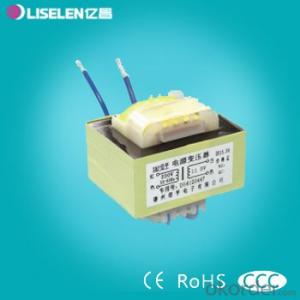

Low frequency EI type Lead Transformer Without Clamping frame
- Ref Price:
-

- Loading Port:
- Tianjin
- Payment Terms:
- TT OR LC
- Min Order Qty:
- 1000 unit
- Supply Capability:
- 50000 unit/month
OKorder Service Pledge
OKorder Financial Service
You Might Also Like


Products can be customized according to customer requirements!

Large, small household electrical appliances, small power industrial products, instrumentation and other industries.

The use of a wide range, high stability, the use of F grade 155 temperature resistance temperature rating materials. Domestic famous brand products of silicon steel sheet. Automated processing and production of shipments to ensure product consistency while improving the quality level.


Company have 21 years of business history, set research and development, production and sales as one of professional transformer manufacturing enterprises, also is transformer industry of Shandong Province CQC certification (the original Great Wall certification system, certification time longest enterprises (14 years), mainly produce and sell all kinds of transformer products, including: (transformer Division) three-phase dry type transformer, intelligent three-phase servo transformers, BK\JBK1\JBK3\JBK5 control transformer, toroidal transformer, (small transformer Division) pin, potting type, lead type power transformer series products. (high-frequency transformer Division) EE series, EFD series, PQ series, filter, I-inductor, loop inductance etc..
We are able to supply various types of terminal blocks according to clients' requirement,Please contact us so we can offer you the best quality,competitive price and timely delivery.
- Q:I understand that transformers used to lower voltage for AC power transmission, simultaneously change both the voltage and current, but if such a transformer were in used in say a 12 volt dc power adapter that plugged into the wall outlet, then it would be counterproductive if the voltage lowering transformer upped the current as too much power would be dissipated, and a current boost would be unwanted, right? Same with transformer for PC power supplies. They must lower voltage without upping the current, right? Thanks a lot.
- For a perfectly efficient (100% efficiency) transformer, [Power before transforming] [Power after transforming] That is V1 I1 V2 I2 Therefore, it DOES up the current when lowering the voltage. However, for a transformer that is not 100% efficient: [Power before transforming] [efficiency in %age]/100) × [Power after transforming] Therefore, for a non-efficient transformer, it is theoretically possible to lower the voltage without upping current. For example for a 50% efficient transformer thet converts 220 V ac at 20A to 110 V: 220 × 20 (50/100) × 110 × x Solve for x: x 20A
- Q:Transformer ratio and transformer ratio
- Transformer ratio K and transformer voltage on both sides U1 U2 winding turns N1 N2 current I1 Ⅰ2 have a relationship! In the ideal case, the ratio K = U1 / U2 = N1 / N2 = I2 / I1
- Q:come on.the battle scenes and all the transformers were totally awesomebut.all the small jokes that sam and his parents and other various characters madejust killed itlike they were actually trying to add a comic element to it.and what is with the transformers cussing? it doesnt feel righttransformers dont cuss.lol
- I haven't seen it, but I heard it was worse than the first one.
- Q:i study transformer and found calculation for pf for open/short circuit test. but the value is bit confusing.pf at open test: 0.182pf at short tets: 0.135what the value means??why we need that??
- The power factor and reactive volt-amperes are only important as intermediate steps to calculating the values of the transformer's equivalent circuit component values. The pf determined in the open circuit test is related to the magnetizing reactance and core loss resistance. The power factor determined in the short circuit test is related to the primary plus secondary leakage reactances and winding resistances. The equivalent circuit component values are needed for various transformer performance calculations and for calculating the influence of the transformer on the complete circuit. I don't believe that the open circuit and short circuit pf and VARs are used for anything once the equivalent circuit has been determined.
- Q:Current and Potential transformers both are actually Instrument transformers, which step down or lower down the values of current and voltages for measuring purposes.But I have heard of that both CT and PT specifically are used for stepping up current and voltages at some point of transmission system.if this is correct then can anyone tell where they are used?If not then there are step up transformers for similar uses but my question is why they are not called as CT's or PT's.
- The usual application of CTs and VTs is to provide isolation between the power system and instrumentation and/or protection equipment. And in this instance, the transformation is usually to reduce the magnitude of the voltage or current that is being measured. There occasionally are instances in which it is necessary to increase the magnitude of voltage or current. In most instances these situations involve relatively minor adjustments in the magnitude of voltage or current and take place in the CT or VT secondary. The transformers that are used to make these adjustments are typically called 'auxiliary' CTs or VTs. There are a few very specialized situations in which CTs or VTs are used to couple a signal into the power system itself. One example of this is where a high-frequency signal is superimposed onto the power system to establish a control communications channel. So-called 'power line carrier' signals are usually in the kHz range, and are typically coupled into the system via VTs - most often, capacitive VTs rather than inductive VTs.
- Q:Branch circuit cables are rated for 75?C and feeder cables are rated for90°C. This will be a 3-phase, 575-volt system with four induction motors, specified asfollows:Motor 1: 60 hp 0.90 p.f. squirrel cage motorMotor 2: 60 hp 0.90 p.f. squirrel cage motorMotor 3: 40 hp 0.85 p.f. wound rotor motorMotor 4: 7-1/2 hp 0.80 p.f. wound rotor motorA) Assuming no line losses, find the capacity of the transformer required to supplypower to this system.B) Assume that it is desired to improve the overall power factor for this system to 0.95lagging. Determine, in kVAR, the required capacitance for this power factorcorrection.C) Assume these motors have their windings connected in a delta configuration. Whatwould be the line voltage if they were connected in wye?
- I would look in the NEC for the full load amperes of these motor sizes. These are: 7.5 HP9 amps 40 HP.41 amps 60 HP.62 amps The 7.5 HP motor KVA will be KVA 575 * 9 * 1.732 8.9631 The 7.5 HP motor KW will be KW 575 * 9 * 1.732 * 0.8 7.17048 The KVAR of this motor is Sqrt(8.9631^2 - 7.1705^2) 5.3778 The 40 HP motor KVA will be KVA 575 * 41 * 1.732 40.8319 The 40 HP motor KW will be KW 575 *41 * 1.732 * 0.8 5 34.707115 The KVAR for this motor is Sqrt(40.8319^2 - 34.7071^2) 21.5095 The 60 HP motor KVA will be KVA 575 * 62 * 1.732 61.7458 The 60 HP motor KW will be KW 575 *62 * 1.732 * 0.8 5 55.5712 The KVAR for this motor is Sqrt(61.7458^2 - 55.5712^2) 26.9141 The total KVA requirement for all motors running at once is 8.9631 + 40.8319 + 61.7458 + 61.7458, which is 173.2866 KVA (note this is the requirement from a transformer, not the size of the transformer The total KW of all the motors is 7.1701 + 34.7071 + 55.5712 + 55.5712 153.0196 KW The total KVAR of all the motors is 5.3778 + 21,5095 + 26,9141 + 26.9141 80.7145 KVAR The power factor for all the motor is KW / KVA 153.0196 / 173.2866 0.883 I took a short cut at this point and used an application i wrote to calculate the required capacitor KVAR. The results follows: At 0.95 power factor, the motors' KVA will be 161.065 The motors' KW will be the same. The motors' KVAR will be 50.2926 The required capacitor's KVAR will be 53.988 The reactance of the capacitor will be 10.65 ohms The capacitance will be 3.49059248 E -4 Farads You can calculate these values as I did above, if you want to. EDIT Forgot the last answer. The line voltage is the same for both delta and wye. The leg voltage for the wye motor will be 575 / 1.732 331.98 volts TexMav
- Q:i want what does a transformer exactly do and not how it works
- A okorder
- Q:I really want to know what a transformer is, how it works, and why it works. I really want an answer that goes down the the atomic scale. I really want analogies. And please don't copy and paste stuff from websites. Please don't worry about getting second comment. The most scientific and well explained answer gets best answer.
- I know this isn't what you asked for, but it gives a much better answer than I'm willing to type.
- Q:I have a 120v-36v transformer hooked up to a bridge rectifier composed of 4x IN4004 diodes, 2 filter capacitors and a 100k resistor paralleling them as a bleeder resistor. The rectifier puts out the full 50v DC I expect it to, but at the same time the transformer faintly vibrates (you can only really tell if you touch it), and over time it gets quite hot. Why is this? I have checked over my connections quite a few times and I am 99.9% sure its all connected properly.
- As Bill R says for working it out. As to how to answer in an exam, First write what is known, and what is wanted down. Write the appropriate equation(s) down and substitute values/simplify equation down as far as possible, you haven't been given all the information required to get that answer in the question. If you don't have all the data provided, and aren't expected to make assumptions then I'd argue the correct answer is actually the formulae produced when you've correctly put all that known in. But quite often you ARE expected to make reasonable assumptions. Sometimes an exam might have a cover page with assumptions to be made (if you don't make them you'll not get the answer right) sometimes you've just got to know how to make reasonable assumptions without being told. as it's 60Hz mains you're probably in the US. I'm in the UK so would it be reasonable for me to assume 50Hz mains if I were sitting the exam here? In cases where you have to make assumptions, it's usually a good idea to then state you are making an assumption. I suggest showing the difference which can happen if f is at least two different values eg finish with assuming f50Hz as mains is in the UK, then C needs to be C1followed on the next line by assuming f60Hz as mains is in the US, then C needs to be C2If you were feeling a little annoyed at those who wrote the exam, and wanted to make your point extra clear you might even throw in the case of f 120Hz. I believe many aircraft alternators generate AC at that f. Ask your teacher/lecturer about what kind of assumptions you might be expected to make. If they skirt around the issue maybe quote some Charles Babbage, and hope they laugh at the sarcasm ' On two occasions I have been asked,—Pray, Mr. Babbage, if you put into the machine wrong figures, will the right answers come out? I am not able rightly to apprehend the kind of confusion of ideas that could provoke such a question.' —Charles Babbage, Passages from the Life of a Philosopher
- Q:I have a standard transformer with 7 wires:2 black2 red2 yellow1 red/yellow stripedWhat connections do these wires correspond to?That is, which should connect internally to the primary coil, the secondary coil, and coil-taps (based on the number of wires, I assume that the secondary coil is tapped).I must determine this in order to connect the wires (externally) appropriately.Any help is greatly appreciated!
- Raptor gave good info. I would add just a few points: 1. The high voltage winding usually has the smaller gauge wire. 2. The high voltage (primary) winding also usually has a higher DC resistance and fundamental frequency impedance than the secondary. 3. Be sure to scrape the insulation off the wires before checking the resistance. Many years ago, an idiot I was working with didn't recognize that the wires had enamel insulation on them, and connected the transformer backwards. It was a 480 V / 1 V (or so) instrument transformer. We lost a lot of good equipment and nearly lost people because of that screwup. The recorder saw 2 kV before it died.
1. Manufacturer Overview |
|
|---|---|
| Location | |
| Year Established | |
| Annual Output Value | |
| Main Markets | |
| Company Certifications | |
2. Manufacturer Certificates |
|
|---|---|
| a) Certification Name | |
| Range | |
| Reference | |
| Validity Period | |
3. Manufacturer Capability |
|
|---|---|
| a)Trade Capacity | |
| Nearest Port | |
| Export Percentage | |
| No.of Employees in Trade Department | |
| Language Spoken: | |
| b)Factory Information | |
| Factory Size: | |
| No. of Production Lines | |
| Contract Manufacturing | |
| Product Price Range | |
Send your message to us
Low frequency EI type Lead Transformer Without Clamping frame
- Ref Price:
-
- Loading Port:
- Tianjin
- Payment Terms:
- TT OR LC
- Min Order Qty:
- 1000 unit
- Supply Capability:
- 50000 unit/month
OKorder Service Pledge
OKorder Financial Service
Similar products


New products


Hot products


Hot Searches

