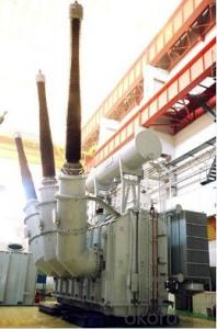
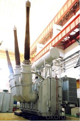
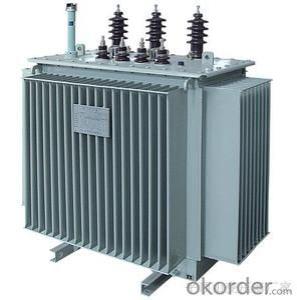
68MVA/500kV standby transformer power plant
- Ref Price:
-

- Loading Port:
- Tianjin
- Payment Terms:
- TT OR LC
- Min Order Qty:
- 1 pc
- Supply Capability:
- 1 pc/month
OKorder Service Pledge
OKorder Financial Service
You Might Also Like


Quick Details
| Place of Origin: | HeBei | Brand Name: | CNBM | Model Number: |
|
| Usage: | Power | Phase: | Coil Structure: | Toroidal | |
| Coil Number: | 3 Winding | Capacity: | Rated Voltage: | 68MVA/500kV | |
| Connection Symbol: | YNd11 Dyn11 YNyn0d11 | Tank: | Cover type or Bell type | OLTC: | MR or ABB or SMS |
Packaging & Delivery
| Packaging Detail: | Mainbody --naked Disassembled parts -- crate |
| Delivery Detail: | 3 months |
Specifications
1. CESI certificate
2. High short-circuit withstand
3. Low loss, PD and noise
4. CTQC certificate
5. No leakage
Description
The application of the 68MVA/500kV standby transformer power plant, and matches well with the transmission capacity of UHV lines, which has wide prospect of application. Because of its large capacity and large volume, the whole transportation weight with nitrogen is about 200-490 tons, and due to the restricted transport conditions, the transportation becomes the critical issue for application of the 68MVA/500kV standby transformer power plant. In order to make the products applicable to any UHV substation in our country, the state grid of corporation of China set the "A study of easy-transport large capacity UHV Transformer” as a key scientific research projects, and entrusted BTW to carry out the research.
During the process of research and development, BTW adopted the advanced design technology and modular design, the transformer can be transported disassembly and with advantages of compact core and winding body, less transportation weight and low transportation cost, effectively solves the need of UHV construction in the transportation restricted areas. By using the most advanced 3D magnetic field calculation software, BTW performed detailed analysis and calculation for the magnetic flux leakage and eddy current loss of the transformer coil, iron core and oil tank steel structures. Besides, by using of the advanced electric field calculation software, BTW performed detailed analysis and calculation of main longitudinal insulation, and mastered the arrangement of the main longitudinal insulation of large capacity UHV transformer and the control of distribution of winding magnetic flux leakage. All of which make the products with low loss, low noise, small volume, strong anti short circuit ability, no local overheating and other significant advantages, and guarantee the long-term safe and stable operation.
The world's first on-site assembled large capacity UHV Transformer’s right at the first time once again filled the gap in the field of UHV transformer research after Chinese transformer industry overcame the difficulty of integral transport of the 68MVA/500kV standby transformer power plant, which marks BTW has fully occupied the world transformer industry technical peak. The successful development of the product filled the gaps in the domestic technology and met the urgent need of UHV construction application in our country, greatly improved the technical level and manufacturing ability of BTW in terms of UHV Transformer products.
- Q:A small transformer used in a foundry has 550 primary turns and 20 secondary turns. Initially, the switch on the secondary side of the transformer is open, so there is no connection between the two ends of secondary coil.(a) What is the voltage difference between the two ends of the secondary coil, Vs, if a direct current potential of Vp 120 V is placed across the primary coil? (That is, the frequency of oscillation on the primary is zero.) (b) What is the voltage difference between the two ends of the secondary coil, Vs if Vp is 120 V and the frequency of oscillation on the primary is 60Hz? (c) Now equipment powered by the transformer is put into use and the switch is closed. A resistance of 14 Ω is placed between the two ends of the secondary coils. What is the current through the secondary coil? (d) What is the current through the primary side of the coil with the switch closed? Thanks so much!!
- A. Zero, since dc current does not have a varying magnetis field. B. 550/120 20/ X 4.3636volts Ne /E p Ns / E s C.4.3636v / 14 .311 a. Es / R t A s D. .011 amp if the transformer is 100% efficient
- Q:I noticed that I haven't seen a female transformers, which leads to two possibilities, they were gay or asexual.
- Hm. Never really thought about it
- Q:Transformers, broken, how to repair
- You can first check the insurance, if only insurance problems, you can short-term insurance; the other can buy a replacement of the same specifications, the coil can also be broken coil rewind.
- Q:1. Which type of connection would be the best to use at the beginning of a power transmission line? Which connection would be the best to use at the end of a power transmission line? Explain.2. In wye delta and wye wye transformation, what line voltage should be applied in order to have all transformer windings operating at their rated voltage?3, how do you calculate the percentage of the line voltages?
- 1. The transformers at both ends of the transmission line are normally connected wye with the neutral grounded. This is done to provide a 'zero sequence source' for two reasons a. to provide source of ground fault current to a fault on the transmission line to permit that fault to be detected. b. to constrain the elevation of voltage on the healthy phases of the transmission line in the event of a ground fault In order for that wye connection to work, it is usually necessary that the transformer also contain a delta winding. 2. The voltage should be the rated line-to-line voltage of the winding. 3. The line-to-neutral voltage is equal to the line-to-line voltage divided by the square root of three. I don't understand what you mean by 'percentage of the line voltages'.
- Q:around the house. Im looking for a step up transformer to handle 1.5VAC-18VAC with a ratio of 1:10 or 1:20. Which household objects would contain this??
- The voltage makes no difference to the transformer but only current the ratio. There are buck boost transfromers that can be bought with only a few dollars that will give you the AC voltage you want. The schemetic is difficult to read with a buck boost transformer but if you know basic electronics then it will be a snap after you sat and thought about it.
- Q:Transformer how to do no load test
- The test voltage of the no-load test is the rated voltage of the low-voltage side. The no-load test of the transformer mainly measures the no-load loss. No-load loss is mainly iron loss. The magnitude of the iron loss can be considered independent of the size of the load, ie the loss at no load is equal to the iron loss at the time of the load, but this is the case when the rated voltage is present. If the voltage deviates from the rated value, the no-load loss and no-load current will change abruptly because the magnetic induction in the transformer core is in the saturation section of the magnetization curve. Therefore, the no-load test should be carried out at rated voltage. Note: In the measurement of large transformer no-load or load loss, because the power factor is very low, can achieve cosφ less than and equal to 0.1. So it is necessary to use low power factor watt table.
- Q:Actually both amplifies the input voltage. A step up transformer amplifies the input voltage and a transistor also amplifies. So what is the differece????
- Easy. A transistor is a semi conductor that can essentially function as an on-ff switch. On certain configurations, you can use a transistor circuit with the right driving voltages to function as an amplifier/ Where as a transformer, is an active lumped circuit element which composed of wound coils, and ferromagnetic elements as a core which steps up or down the voltage of an electrical current by mutual induction. The principles behind both are VERY different, both in function, understanding and operation. Hope I helped some :)
- Q:How does the core material affect a transformer? Such as if you use steel vs. air. Or wood vs. magnet.
- In 50 or 60 Hz transformers putting in a laminated magnetic iron core greatly increases the amount of magnetic flux which is generated by the primary current with the secondary on open circuit (the so called magnetising current). This enables the windings to generate a relatively high voltage with relatively small magnetising current. If you tried to make a 50/60 Hz transformer without a magnetic core (with say air or any other non-magnetic insulating material) it virtually wouldn't work because the magnetising current would be so high (the primary winding practically a short circuit). If you used a non-magnetic conducting material you'd be even worse off because eddy currrents generated in the material would prevent any flux being established and you'd have plenty of core heating but no coupling between primary and secondary. For this reason even the iron core must be laminated (unless it's non-conducting ferrite). The story is quite different for high frequencies where the inductive impedances of coils are enhanced by the frequency. There you can make quite effective air cored transformers; small ones at least - but you'd still better avoid conducting material in the core - that's what food is in a microwave oven; conducting material in the core of a high fequency transformer.
- Q:100kVA transformer can withstand much of the current? What is its formula?
- For safety insurance, the current density is about 3.0, S = 144.34 / 3 = 50 (about) So take the 50 square cable can be.
- Q:I have halogen lights in my basement. When i mean contact i am talking about this little hanging jack where by you plug in the light bulb into. For some reason, one of my lights are not working properly but I have already tested the light bulbs out. I have a feeling that the contact/transformer (hanging jack slot) is ineffective. Does anybody have an idea how to change these things?
- You are putting too much energy into the transformer. You need a circuit breaker in your circuit in order to reduce the amount of power that goes through the transformer. Because so much power is going through the transformer, it can only put out so much, so fast, and, therefore, your halogen lights are not turning it on. You can google circuit breakers or resistors, or take the lights in to any hardware store to see if they can fix them.
1. Manufacturer Overview |
|
|---|---|
| Location | |
| Year Established | |
| Annual Output Value | |
| Main Markets | |
| Company Certifications | |
2. Manufacturer Certificates |
|
|---|---|
| a) Certification Name | |
| Range | |
| Reference | |
| Validity Period | |
3. Manufacturer Capability |
|
|---|---|
| a)Trade Capacity | |
| Nearest Port | |
| Export Percentage | |
| No.of Employees in Trade Department | |
| Language Spoken: | |
| b)Factory Information | |
| Factory Size: | |
| No. of Production Lines | |
| Contract Manufacturing | |
| Product Price Range | |
Send your message to us
68MVA/500kV standby transformer power plant
- Ref Price:
-
- Loading Port:
- Tianjin
- Payment Terms:
- TT OR LC
- Min Order Qty:
- 1 pc
- Supply Capability:
- 1 pc/month
OKorder Service Pledge
OKorder Financial Service
Similar products


New products


Hot products


Hot Searches
Related keywords

