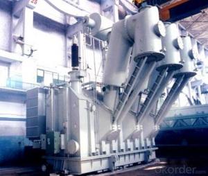

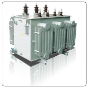
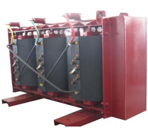
40MVA/220KV startup/standby OLTC transformer
- Ref Price:
-

- Loading Port:
- Tianjin
- Payment Terms:
- TT OR LC
- Min Order Qty:
- 1 pc
- Supply Capability:
- 1 pc/month
OKorder Service Pledge
OKorder Financial Service
You Might Also Like


Quick Details
| Place of Origin: | HeBei | Brand Name: | CNBM | Model Number: |
|
| Usage: | Power | Phase: | Coil Structure: | Toroidal | |
| Coil Number: | 3 Winding | Capacity: | Rated Voltage: | 40MVA/220KV | |
| Connection Symbol: | YNd11 Dyn11 YNyn0d11 | Tank: | Cover type or Bell type | OLTC: | MR or ABB or SMS |
Packaging & Delivery
| Packaging Detail: | Mainbody --naked Disassembled parts -- crate |
| Delivery Detail: | 3 months |
Specifications
1. CESI certificate
2. High short-circuit withstand
3. Low loss, PD and noise
4. CTQC certificate
5. No leakage
Description
The application of the 40MVA/220KV startup/standby OLTC transformer, and matches well with the transmission capacity of OLTC lines, which has wide prospect of application. Because of its large capacity and large volume, the whole transportation weight with nitrogen is about 200-490 tons, and due to the restricted transport conditions, the transportation becomes the critical issue for application of the 40MVA/220KV startup/standby OLTC transformer. In order to make the products applicable to any OLTC substation in our country, the state grid of corporation of China set the "A study of easy-transport large capacity OLTC Transformer” as a key scientific research projects, and entrusted BTW to carry out the research.
During the process of research and development, BTW adopted the advanced design technology and modular design, the transformer can be transported disassembly and with advantages of compact core and winding body, less transportation weight and low transportation cost, effectively solves the need of OLTC construction in the transportation restricted areas. By using the most advanced 3D magnetic field calculation software, BTW performed detailed analysis and calculation for the magnetic flux leakage and eddy current loss of the transformer coil, iron core and oil tank steel structures. Besides, by using of the advanced electric field calculation software, BTW performed detailed analysis and calculation of main longitudinal insulation, and mastered the arrangement of the main longitudinal insulation of large capacity OLTC transformer and the control of distribution of winding magnetic flux leakage. All of which make the products with low loss, low noise, small volume, strong anti short circuit ability, no local overheating and other significant advantages, and guarantee the long-term safe and stable operation.
The world's first on-site assembled large capacity OLTCTransformer’s right at the first time once again filled the gap in the field of OLTC transformer research after Chinese transformer industry overcame the difficulty of integral transport of the 40MVA/220KV startup/standby OLTC transformer, which marks BTW has fully occupied the world transformer industry technical peak. The successful development of the product filled the gaps in the domestic technology and met the urgent need of UHV construction application in our country, greatly improved the technical level and manufacturing ability of BTW in terms of OLTC Transformer products.
- Q:if the transformer converts 240v ac to 8V ac, ratio 30:1 then it should step up the voltage by the same ratio, i.e, 15V ac to 450v ac.but it's not the case !!
- It will, but you have to realize that the series resistance of the primary (which is now your secondary) is getting in the way. I am going to guess that this is a very small transformer, capable of one or two VA at most. The rating is a little tricky too. A 240V-8V transformer puts out a significantly higher voltage, maybe 20-30V, with no load. It's rated at 15V because under a load, with magnetic and resistance losses, the effective turns ratio is lower. Used in reverse, the opposite problem exists, because your actual turns ratio is much higher than 30:1. Edit: If it wasn't for silly ideas a lot of inventions wouldn't have been made. The secondary probably doesn't have enough turns to provide adequate self-inductance at 240 volts. It would just act like a short and burn out. There is also a possibility that there is not enough dielectric strength between adjacent windings or the frame to prevent arcing, but most transformers are designed to withstand thousands of volts so this is less likely. If possible, I'd recommend trying lower voltages (perhaps 8V from another transformer), and measuring the current with the primary (now the secondary) open. Put a load resistor in there to start just in case. If you're drawing more than a few milliamps, don't try hooking it up to the mains.
- Q:What is the rated current of the 80KVA transformer?
- Rated current formula: I = P / 1.732 × U = 80000 / 1.732 × 380 ≈ 122 (A) (Current contains active and reactive current)
- Q:I have contacted Crate and they gave me a list of parts dealers but all insist that they do repairs and not sell just power transformers. I am looking for a part #94-029-01. Thank you for any help!!
- First, what you need to know is the secondary voltages of the transformer you wish to replace. A part number is nice, but tells you very little, unless you have a book on hand, and usually, these numbers are only for that product line (in house) part numbers. I can tell you where to go to find a power x-fmr. but will need to know: How many watts will said amplifire send to the speakers, how many wires come off of the secondary, and how big is it? If you can get a schematic drawing of your amplifire with power transformer output voltages, I can tell you exactly where to get a transformer from. Feel free to e-me. Why did it fail? Are you sure that the power transformer is bad? There may be other issues, here. I rarely see a transformer go bad under normal use. If the fuse blows, replace it with a 1/2 amp larger than it calls for. If it calls for a 2 amp fuse, try a 2.5 amp fuse. If it still blows, try a 3. if it still blows, you may have a short in the power output section of your amp. I don't normally recommend that higher fuse ratings should be used, but that is what I would do if I was working on it. You may find other issues besides the power transformer. If you have voltage going into (the primary) and no voltage on the secondary at all, then you might have a transformer that has a thermal cutoff unit that is hooked up in series with the primary windings protecting the transformer from over heating. This has been known to happen, and can be easily repaired, if you have the right tools, a soldering iron, and a lot of patience. I can walk you through it.
- Q:Is the transformer a power adapter?
- Power adapter is a transformer, it should be said that the power adapter is a transformer, rather than that the transformer is a power adapter. Like Baidu is the site, the site is not Baidu ah.
- Q:Transformer short-circuit impedance is big good, or small good? The same capacity, voltage ... solution
- Transformer rated current / short circuit impedance = transformer short-circuit current 6% short-circuit current is small, and 4% not much difference, personal point of view! Nothing can look at Guo Weiguo teacher answered the question, will certainly benefit from the.
- Q:What is the maximum current of the 800KVA transformer? What is the current? Is how to calculate, ask you master
- 10KV / 0.4KV, 800KVA Transformer rated current is: High pressure side, I = 800 / (1.732 * 10) = 46.2A Low pressure side, I = 800 / (1.732 * 0.4) = 1154.7A Low side of the economic current is about: 1154.7 * 70% = 808.3A
- Q:Briefly explain how an alternating current transformer works and why they are so important to the world’s electrical power infrastructure.
- Okay. You take a magnet and run it past a coil and you get electricity. You can also simply switch the direction of current (or pulse it) in order to create induction current in a coil. So. if you make a basic AC electromagnet with say. 100 loops of thick copper wiring, and put it next to another coil with say. 10,000 thinner wraps. The coil that gets the juice, will induce a current in the coil next to it. Conveniently, more wraps higher voltage lower amperage, and fewer wraps higher amperage lower voltage. So in the above scenario, under ideal circumstances, we would take a primary voltage off 100 volts 100 amps and turn it in to a stepped-up voltage of 10,000 volts at one amp. The reason this is important is that high voltage travels well over great distances. It is much easier to push the same juice much farther away from its source with very high VOLTAGE and low amps than it is to do it the other way. Amps cause heat, heat causes loss and damage to the carrier wire. Voltage just rides along on the surface of the wire with very little loss. So we step up for transport and back down for use when we are close enough to end-use that the losses are negligible.
- Q:Is the transformer a power supply?
- In the classification of electrical components, the transformer does not belong to the power supply, belonging to the power conversion element
- Q:As a small project I wish to wire a microwave transformer to create arcs in air via use of a wand (and yes I will be taking the necessary precautions but that's step 2) first I need to know a couple things: 1 on the high voltage secondary is it really as simple as take the two leads and put them anywhere near eachother? Would that not create a MASSIVE short circuit? Most of the tutorials I've seen use in series so perhaps that negates it in some way? Or am I reading it wrong? Is there some sort of safe load used? Or does it really arc to itself? And 2 what is a good way of preventing it from overheating (if that is a problem). This will probably be used as a Jacob's ladder or old motherboard destroyer. Thanks so much for the help!
- here you go
- Q:I have a question can someone explain why transformers get hot in use and why must they not be allowed to get too hot
- They get hot because like pretty much everything, they are not 100% efficient. When a transformer is powered on, even if there is no load on it there is something called iron losses - this is the amount of energy which is used to magentise the iron core of the transformer. These losses end up as heat. When the transformer has to start delivering power to the load, there are also copper losses to consider, this is because as more power flows through the windings, because the wire is not a perfect conductor, some heating of the copper winding occurs ( these losses are sometimes known as I squared R - meaning current x current x resistance) Iron losses are fixed, copper losses increase as the amount of power taken from the transformer increases. As for why you must not let them get to hot, from a functional point of view, above a certain temperature (varies according to insulation used) the enamel and other insulativbe properties will break down and you then get a shorted transfomer. Not helpful A second reason is for safety, some transformers will reach temperatures EXCEEDING the ignition temperature of flammable material - so in simple terms, a fire risk. Usually a transfomer has a thermal fuse fitted so that under overload conditions, it will rupture the fuse rather than get dangerously hot. Mark
1. Manufacturer Overview |
|
|---|---|
| Location | |
| Year Established | |
| Annual Output Value | |
| Main Markets | |
| Company Certifications | |
2. Manufacturer Certificates |
|
|---|---|
| a) Certification Name | |
| Range | |
| Reference | |
| Validity Period | |
3. Manufacturer Capability |
|
|---|---|
| a)Trade Capacity | |
| Nearest Port | |
| Export Percentage | |
| No.of Employees in Trade Department | |
| Language Spoken: | |
| b)Factory Information | |
| Factory Size: | |
| No. of Production Lines | |
| Contract Manufacturing | |
| Product Price Range | |
Send your message to us
40MVA/220KV startup/standby OLTC transformer
- Ref Price:
-
- Loading Port:
- Tianjin
- Payment Terms:
- TT OR LC
- Min Order Qty:
- 1 pc
- Supply Capability:
- 1 pc/month
OKorder Service Pledge
OKorder Financial Service
Similar products


New products

Hot products


Hot Searches
Related keywords

