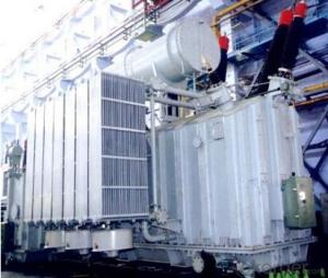
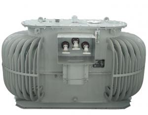
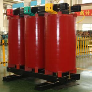
250MVA/220kV standby transformer power station
- Ref Price:
-

- Loading Port:
- Tianjin
- Payment Terms:
- TT OR LC
- Min Order Qty:
- 1 pc
- Supply Capability:
- 1 pc/month
OKorder Service Pledge
OKorder Financial Service
You Might Also Like


Quick Details
| Place of Origin: | HeBei | Brand Name: | CNBM | Model Number: |
|
| Usage: | Power | Phase: | Three | Coil Structure: | Toroidal |
| Coil Number: | 3 Winding | Capacity: | Rated Voltage: | 250MVA/220kV | |
| Connection Symbol: | YNd11 Dyn11 YNyn0d11 | Tank: | Cover type or Bell type | OLTC: | MR or ABB or SMS |
Packaging & Delivery
| Packaging Detail: | Mainbody --naked Disassembled parts -- crate |
| Delivery Detail: | 3 months |
Specifications
1. CESI certificate
2. High short-circuit withstand
3. Low loss, PD and noise
4. CTQC certificate
5. No leakage
Description
The application of the 250MVA/220kV standby transformer power station, and matches well with the transmission capacity of UHV lines, which has wide prospect of application. Because of its large capacity and large volume, the whole transportation weight with nitrogen is about 470-490 tons, and due to the restricted transport conditions, the transportation becomes the critical issue for application of the 250MVA/220kV standby transformer power station. In order to make the products applicable to any UHV substation in our country, the state grid of corporation of China set the "A study of easy-transport large capacity UHV Transformer” as a key scientific research projects, and entrusted BTW to carry out the research.
During the process of research and development, BTW adopted the advanced design technology and modular design, the transformer can be transported disassembly and with advantages of compact core and winding body, less transportation weight and low transportation cost, effectively solves the need of UHV construction in the transportation restricted areas. By using the most advanced 3D magnetic field calculation software, BTW performed detailed analysis and calculation for the magnetic flux leakage and eddy current loss of the transformer coil, iron core and oil tank steel structures. Besides, by using of the advanced electric field calculation software, BTW performed detailed analysis and calculation of main longitudinal insulation, and mastered the arrangement of the main longitudinal insulation of large capacity UHV transformer and the control of distribution of winding magnetic flux leakage. All of which make the products with low loss, low noise, small volume, strong anti short circuit ability, no local overheating and other significant advantages, and guarantee the long-term safe and stable operation.
The world's first on-site assembled large capacity UHV Transformer’s right at the first time once again filled the gap in the field of UHV transformer research after Chinese transformer industry overcame the difficulty of integral transport of the 250MVA/220kV standby transformer power station, which marks BTW has fully occupied the world transformer industry technical peak. The successful development of the product filled the gaps in the domestic technology and met the urgent need of UHV construction application in our country, greatly improved the technical level and manufacturing ability of BTW in te
Core: The three-phase three-pillar structure inside and outside the box rolling. Center column for the multi-step cross section. After rolling core using vacuum annealing to remove stress, bending clamping groove. Pull screw to tension the body. Core surface brush special angle glue, to ensure core is not deformed and not rust.
Coil and the body: low-voltage coil made up of 1 to 6 wires together to four layers or double-cylinder type (500KVA and below), or spiral-type. High voltage coil axial direction Oil conduit and high-low voltage main oil gap are Stays curtain structure. Iron yoke insulation and trapezoid pads as one, so that the body uniform compression, body structure using the new safety board positioning, vertical and horizontal orientation, ensuring that is no displacement.
Tank: The ripple tank, sealed structure, no leakage, maintenance-free.
Our service
1. Before the order, you will be provided with our general product descriptions, a series of detailed account for commodity, instructions, quotation sheet and related qualification certificate to have a knowledge of our company and products.
2. After signing the technical agreement, the general assembly drawing, base drawing, drawing information and technical requirements will be offered. The technical requirements of agreement will be implemented strictly to provide new, advanced, mature and reliable products.
3. Guarantee all the process, components, accessories and test for products comply with the national standard or client-specified standard.
4. After products arriving, technicians will be sent to investigate on the site installation supervision, insure the perfect installation in the shortest possible time. During the debugging period, we also assist in the field test and debugging to make sure it running smoothly.
5. The technicians are responsible for the explaining of technical documents and drawing and answering and solving all problems about our products.
1. Manufacturer Overview |
|
|---|---|
| Location | |
| Year Established | |
| Annual Output Value | |
| Main Markets | |
| Company Certifications | |
2. Manufacturer Certificates |
|
|---|---|
| a) Certification Name | |
| Range | |
| Reference | |
| Validity Period | |
3. Manufacturer Capability |
|
|---|---|
| a)Trade Capacity | |
| Nearest Port | |
| Export Percentage | |
| No.of Employees in Trade Department | |
| Language Spoken: | |
| b)Factory Information | |
| Factory Size: | |
| No. of Production Lines | |
| Contract Manufacturing | |
| Product Price Range | |
Send your message to us
250MVA/220kV standby transformer power station
- Ref Price:
-
- Loading Port:
- Tianjin
- Payment Terms:
- TT OR LC
- Min Order Qty:
- 1 pc
- Supply Capability:
- 1 pc/month
OKorder Service Pledge
OKorder Financial Service
Similar products


New products

Hot products


Hot Searches
Related keywords

