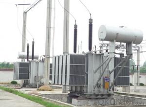
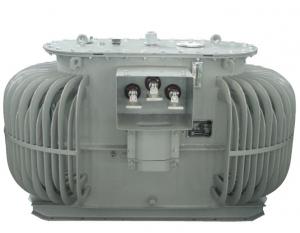
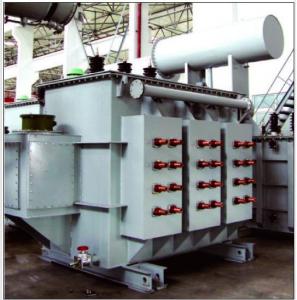
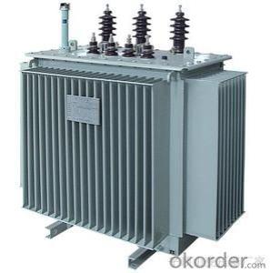
220kV single phase traction transformer of AT power supply railway
- Ref Price:
-

- Loading Port:
- Tianjin
- Payment Terms:
- TT OR LC
- Min Order Qty:
- 1 pc
- Supply Capability:
- 1 pc/month
OKorder Service Pledge
OKorder Financial Service
You Might Also Like


Quick Details
| Place of Origin: | HeBei | Brand Name: | CNBM | Model Number: |
|
| Usage: | Power | Phase: | Three | Coil Structure: | Toroidal |
| Coil Number: | 3 Winding | Capacity: | Rated Voltage: | 25MVA/110kV | |
| Connection Symbol: | YNd11 Dyn11 YNyn0d11 | Tank: | Cover type or Bell type | OLTC: | MR or ABB or SMS |
Packaging & Delivery
| Packaging Detail: | Mainbody --naked Disassembled parts -- crate |
| Delivery Detail: | 3 months |
Specifications
1. CESI certificate
2. High short-circuit withstand
3. Low loss, PD and noise
4. CTQC certificate
5. No leakage
Description
The application of the 25MVA/110kV railway balance traction transformer, and matches well with the transmission capacity of UHV lines, which has wide prospect of application. Because of its large capacity and large volume, the whole transportation weight with nitrogen is about 470-490 tons, and due to the restricted transport conditions, the transportation becomes the critical issue for application of the 25MVA/110kV railway balance traction transformer. In order to make the products applicable to any UHV substation in our country, the state grid of corporation of China set the "A study of easy-transport large capacity UHV Transformer” as a key scientific research projects, and entrusted BTW to carry out the research.
During the process of research and development, BTW adopted the advanced design technology and modular design, the transformer can be transported disassembly and with advantages of compact core and winding body, less transportation weight and low transportation cost, effectively solves the need of UHV construction in the transportation restricted areas. By using the most advanced 3D magnetic field calculation software, BTW performed detailed analysis and calculation for the magnetic flux leakage and eddy current loss of the transformer coil, iron core and oil tank steel structures. Besides, by using of the advanced electric field calculation software, BTW performed detailed analysis and calculation of main longitudinal insulation, and mastered the arrangement of the main longitudinal insulation of large capacity UHV transformer and the control of distribution of winding magnetic flux leakage. All of which make the products with low loss, low noise, small volume, strong anti short circuit ability, no local overheating and other significant advantages, and guarantee the long-term safe and stable operation.
The world's first on-site assembled large capacity UHV Transformer’s right at the first time once again filled the gap in the field of UHV transformer research after Chinese transformer industry overcame the difficulty of integral transport of the 25MVA/110kV railway balance traction transformer, which marks BTW has fully occupied the world transformer industry technical peak. The successful development of the product filled the gaps in the domestic technology and met the urgent need of UHV construction application in our country, greatly improved the technical level and manufacturing ability of BTW in terms of UHV Transformer products.
Core: The three-phase three-pillar structure inside and outside the box rolling. Center column for the multi-step cross section. After rolling core using vacuum annealing to remove stress, bending clamping groove. Pull screw to tension the body. Core surface brush special angle glue, to ensure core is not deformed and not rust.
Coil and the body: low-voltage coil made up of 1 to 6 wires together to four layers or double-cylinder type (500KVA and below), or spiral-type. High voltage coil axial direction Oil conduit and high-low voltage main oil gap are Stays curtain structure. Iron yoke insulation and trapezoid pads as one, so that the body uniform compression, body structure using the new safety board positioning, vertical and horizontal orientation, ensuring that is no displacement.
Tank: The ripple tank, sealed structure, no leakage, maintenance-free.
Our service
1. Before the order, you will be provided with our general product descriptions, a series of detailed account for commodity, instructions, quotation sheet and related qualification certificate to have a knowledge of our company and products.
2. After signing the technical agreement, the general assembly drawing, base drawing, drawing information and technical requirements will be offered. The technical requirements of agreement will be implemented strictly to provide new, advanced, mature and reliable products.
3. Guarantee all the process, components, accessories and test for products comply with the national standard or client-specified standard.
4. After products arriving, technicians will be sent to investigate on the site installation supervision, insure the perfect installation in the shortest possible time. During the debugging period, we also assist in the field test and debugging to make sure it running smoothly.
5. The technicians are responsible for the explaining of technical documents and drawing and answering and solving all problems about our products.
6. After sale, our company will make our every effort to fix the products and make sure it put into operation in time if any malfunction caused during the quality guarantee period.
7. We will keep the record of our clients and keep track of our sold products regularly, so that problems can be solved promptly.
Disclaimer
Warranty or exchange does not apply under the following circumstances.
1) Damage caused by your failure to operation and maintenance.
2) Damage caused by power fail.
3) Damage caused by the maintenance or dismantle movement of a non-our-company authorized maintainer.
4) Damage caused by Natural disasters and other force majeure reasons such as earthquakes, fires.
- Q:The total power of 590kw, this transformer can bear it? It is best to give a formula, do not copy the.
- 600KVA box can generally increase the number of households with electricity
- Q:TN-S system in the transformer neutral point that pe line and n-line neutral point how to take? N line and pe line in the neutral point on the connected, and then ground the same ground? Or that n line from the neutral point out of their own then a pe line then one after another? If the neutral point out of the ground, in the three-phase imbalance when the n-line current?
- TN-S way power supply system It is the work of the zero line and dedicated protection line PE strictly separate power supply system, N line and PE line in the transformer working ground once separated, not to re-connect. Called TN-S power supply system. The TN-S power supply system is characterized as follows. 1) When the system is running normally, there is no current on the dedicated protection line, but there is an unbalanced current on the working zero line. PE line to ground no voltage, so the electrical equipment metal shell connected to zero protection is connected to the dedicated protection line PE, safe and reliable. 2) The working zero line is used only as a single-phase load circuit. 3) Dedicated protection line PE is not allowed to break, but also not allowed to enter the leakage switch. 4) the use of leakage on the trunk protection, the work of the zero line shall not have repeated grounding, and the PE line has repeatedly grounded, but not through the leakage protection, so TN-S system power supply lines can also be installed on the leakage protection. 5) TN-S power supply system is safe and reliable, suitable for industrial and civil construction and other low-voltage power supply system. In the construction work before the "three links and one leveling" (Dentsu, water, road and ground level - must use TN-S way power supply system.
- Q:I have an RCA 46 inch projection Tv model p46924 that doesn't turn on. Someone said I probably need a new transformer. What is it? What does it do? Where is it located?
- Unless the someone was an experienced TV Tech you can take his ( or her ) diagnosis with a very large pinch of salt ! To answer your basic question though what is a Tv transformer ? I will list a few transformers that can be found in a TV set.! Mains AC transformer already described by TV Guy ! Sound IF transformers ( 2 or 3 ) Vision IF transformers Power supply switching transformer ! Line drive transformer . Flyback Transformer A couple or so in the tuner unit. No doubt I have missed a couple and will be picked up on it by the other TV Techs who may decide to answer this question but you get the idea don`t you !! Cheers Pete To be fair Adrian he did say with other circuitry . Cheers Pete
- Q:I heard that a transformer is like a ratio device for amps and volts, but I know there must be more to it. How exactly does it work, and what happens when it doesn't have enough current, but enough voltage?
- A transformer is a pretty simple device, it consist of two or more windings around a iron or ferret core. First keep in mind only AC works in a transformer. Transformers work by the primary winding generating a magnetic flux in the core. The second winding will pick up this flux and convert it back to voltage. Note: Michael Faraday in 1831 discovered this interaction which made transformer, motors and generators possible. Basic rule: Power in Power out - some losses. The ratio of the turns on the primary to the secondary will determine the increase. ie 10 turn on a primary and 100 turn on a secondary will step the voltage up x 10. The turns ratio control the step up or step down of the transformer. More winding on the secondary than the primary will cause a step up of voltage, Less winding will step down. The current carrying capacity of the transformer is controlled by the size of the wire. If you exceed the current carrying capacity you will burn out the winding. Heaver wire can handle more current. I know you have been interested in High Voltage step up transformers. The most voltage a transformer can produce is about 12KV. Usually after that it become extremely difficult to isolate the wires in the secondary to keep the current from jumping from one winding to another and burning out the transformer. The way to step up the voltage after the transformer is to use a voltage multiplier cascade.
- Q:Find full load current of transformer. What do it mean by full load current? 100% efficiency, or maximum load in secondary winding?Let R1 32ohm, R20.05ohm, X1 45ohm, X2 0.06ohm.1 is in primary and 2 in secondary winding.R0250kohm, Xm 30kohm(R0 and Xm are the values refered to primary)How to calculate the full load current?
- there are many criterion it is application dependant or power it is the load that causes a temperature rise that if loaded beyond it will cause failure of course it depends on the insulation material so a smaller transformer could have a much higher rating because it can stand more heat small electronic stuff will generally be when the transformer can no longer sustain the output voltage Anita
- Q:Rules for the operation of cooling devices for oil - cooled transformers
- E, strong oil cycle air-cooled and strong oil circulating water-cooled transformers, when the cooling system failure to remove all the cooler, allowing the rated load to run for 20 minutes, such as 20 minutes after the top of the oil temperature has not reached 75 ℃, then allowed to rise to 75 ℃ , But in this state the maximum time to run no more than 1 hour. ?F, under normal circumstances, the transformer no-load operation, the cooling device two groups of work, a group of auxiliary, a group of spare, the remaining disabled; transformer low temperature, light load, the four groups of work: a group of auxiliary, a group of spare, the rest Deactivated; transformer high temperature, full load, a group of auxiliary, a group of spare, the rest all into work.
- Q:My device has 50KW should be used with much transformer
- Equipment is 50KW? That is to say there are other electrical appliances, you put all the power are considered, a total of how much KW, must start the current is 16 times the original current ah.
- Q:Is the LTC transformer a regulated voltage transformer?
- OLTC (on load tap changer) On-load tap-changer NLTC (no Load tap changer) No load regulator The above two switch switches are used for transformer voltage regulation.
- Q:What is the main purpose of the transformer?
- Second, the loss of the transformer When the primary winding of the transformer is energized, the magnetic flux generated by the coil flows at the core because the core itself is a conductor and the potential is induced on the plane perpendicular to the line of magnetic force. This potential forms a closed loop on the cross section of the core and generates a current, As if a vortex was called "vortex". This "eddy current" increases the loss of the transformer and increases the temperature rise of the transformer's core heating transformer. The loss caused by "eddy currents" is called "iron loss". In addition to the need to use a large number of transformer transformer copper wire, the existence of these copper wire resistance, the current flow through this resistance will consume a certain power, this part of the loss is often turned into heat and consumption, we call this loss " The So the temperature rise of the transformer is mainly caused by iron loss and copper loss. Since the transformer has an iron loss and a copper loss, its output power is always less than the input power. For this reason, we introduce an efficient parameter to describe this, η = output power / input power.
- Q:hi guys can any of you give me advice on wot i need 2do on removing and replacing a faulty line output transformer on a rear veiw projection tv as i have the part and the local tv shop wont fix it 4 me.wot would be the best way to discharge the power from it first and could i jus cut the 2 wires on the old 1 and use connector blocks to connect the new 1 in would this be ok to do or do it need to soilder connected on?. and is there any adjustments that would need to be done to the set when i have it installed be4 i turn it on any help much appreicated
- If you have an identical replacement transformer there shouldn't be a need to adjust anything to start. As to cutting wires to remove the old transformer to replace the new one, I suggest you make yourself a chart of any color coding of the wires or tagging them so there is no error as to what to connect to what on the new transformer. I personally would replace the transformer as the manufacturer installed the original one. As for discharging, use a 10K ohm resistor with one side to ground and the other side of the resistor to the components you want to discharge. I don't advise just grounding direct. Good luck and be careful.
1. Manufacturer Overview |
|
|---|---|
| Location | |
| Year Established | |
| Annual Output Value | |
| Main Markets | |
| Company Certifications | |
2. Manufacturer Certificates |
|
|---|---|
| a) Certification Name | |
| Range | |
| Reference | |
| Validity Period | |
3. Manufacturer Capability |
|
|---|---|
| a)Trade Capacity | |
| Nearest Port | |
| Export Percentage | |
| No.of Employees in Trade Department | |
| Language Spoken: | |
| b)Factory Information | |
| Factory Size: | |
| No. of Production Lines | |
| Contract Manufacturing | |
| Product Price Range | |
Send your message to us
220kV single phase traction transformer of AT power supply railway
- Ref Price:
-
- Loading Port:
- Tianjin
- Payment Terms:
- TT OR LC
- Min Order Qty:
- 1 pc
- Supply Capability:
- 1 pc/month
OKorder Service Pledge
OKorder Financial Service
Similar products


New products


Hot products

Hot Searches
Related keywords

