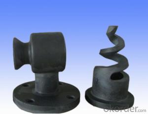


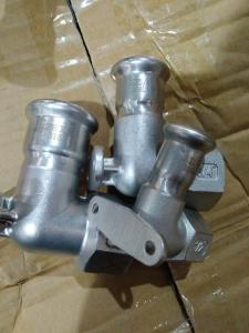
SSIC Silicon carbide nozzle
- Ref Price:
-

- Loading Port:
- China main port
- Payment Terms:
- TT OR LC
- Min Order Qty:
- 5 m.t
- Supply Capability:
- 50 m.t/month
- Option:
- order
OKorder Service Pledge
OKorder Financial Service
You Might Also Like
Item specifice


Tailor-made for customers all kinds of pumps with my company, kettle, bearing no pressure sintering silicon carbide mechanical seal, and all kinds of resistance corrosion pump parts and the accessories. Our company pressureless sintered silicon carbide products a reaction bonded silicon carbide products, can easily adapt to the harsh working conditions, in strong corrosive, strong wear, high temperature, high pressure, high strength harsh harsh under complex conditions is more outstanding. At the same time, our company to provide customers with nozzles, armored body armor plate and other special-shaped pieces of custom-made service.
Compared with the reaction sintered silicon carbide product (SSIC), the production process of the sintered silicon carbide product (RBSIC) is complex and the production investment is high. In addition, whether it is in the resistance to corrosion and abrasion, compressive and flexural fracture resistance of or high pressure, high temperature and other properties are more excellent, this is pressureless sintering silicon carbide products will in the near future completely replace reaction bonded silicon carbide products is one of the important reasons. The main varieties of the pressureless sintering silicon carbide products with all kinds of mechanical seal with sealing ring and moving ring and static ring, corrosion resistant pump, magnetic pump, shield pump components. At the same time, the production special-shaped pieces of nozzle, wire drawing die, armor plate. According to the drawings, we will provide customers with satisfactory products and customer satisfaction. Let customer satisfaction is one of the purposes of our company has been pursued, but also one of the objectives pursued by all the staff of our company.
Features: high temperature resistance, wear resistance, corrosion resistance, oxidation resistance, hardness, heat conduction
Main products: mechanical seals, pump parts, nozzles, bullet proof plate
Mechanical seals: high hardness, high wear resistance, good self - Lubrication and high heat conductivity, so the service life of mechanical seal is greatly improved.
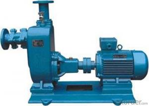
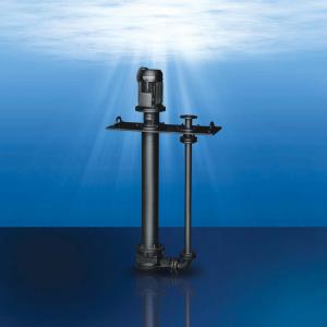
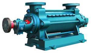
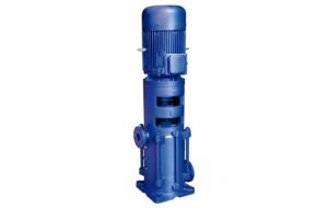
Pump: resistance to corrosion and wear characteristic of the pressureless sintering silicon carbide become magnetic pump sliding bearing, resistant corrosion pump sleeve, shielding pump assembly, etc. various kinds of pump of choice
Nozzle: wear resistant, high temperature resistance, high hardness characteristics of the normal pressure sintering silicon carbide nozzle to become a perfect alternative to carbide nozzle
Armor: light weight, high hardness, good ballistic performance, pressureless sintering of SiC for your life and property security escort
Here are some of the pressure sintered silicon carbide products, physical and chemical parameters:
medium | content | Causticity | |||||||
Atmospheric SIC | The reaction SIC WC | WC | AL2O3 | ZrO2 | Si3N4 | stainless steel | steel | ||
HNO3 nitric acid | 50% | A | A | C | A | A | C | C | C |
Hydrochloric acid HCI | 35% | A | A | C | A | A | C | C | A |
Sulfuric acid H2SO4 | 98% | A | A | C | A | A | C | C | A |
Hydrofluoric acid HFF | 40% | A | C | C | C | C | C | C | C |
Phosphoric acid H5PO4 215OC | 85% | C | C | C | C | C | C | C | C |
HNO3+HF | 20%+5% | A | C | C | C | C | C | C | C |
Sodium chlorate NaCIO | 10% | A | B | C | A | A | A | C | A |
Sodium hydroxide NaOHH | 50% | A | C | A | B | A | B | A | A |
Potassium hydroxide KOH | A | C | A | B | A | B | A | A | |
Acetic acid CH3COOHH | 80% | A | A | C | A | A | C | C | C |
Sodium sulfate + Na2CO3 + H2SO4 925OC
| A | A | C | A | A | C | C | B | |
Silica solution SIO2
| B | C | C | C | C | C | |||
Assessment Method: the specimen prior polishing, immersed in the test liquid (70OC) for 100 hours, the weight was measured and observed microstructure, weight reduction is calculated by the degree of corrosion was observed microstructure for corrosion to comprehensive judgments. | |||||||||
A level (corrosion): corrosion rate ≤0.125mm / ingredients in a small amount of corrosion observed slice | |||||||||
Level B (somewhat resistant): corrosion rate = 0.125-1.0mm / or annual corrosion rate ≤0.125mm / observe a large number of corrosion | |||||||||
Class C (resistant to corrosion): corrosion rate ≥1.0mm / or the main ingredient of Corrosion
Silicon carbide performance indicators
Index Name
| Atmospheric SiC | Reaction Bonded Silicon Carbide |
Purity (%) of silicon carbide | > 97 | >90 |
Density (g / cm) | 3.06-3.15 | >3.05 |
Particle size (um) | 0.5-0.7 | 8-20 |
Hardness (HRA) | ≥90 | ≥90 |
Flexural Strength (MPa) | 400-580 | 350-450 |
Compressive strength (MPa) | 3900 | >2500 |
Fracture Strength (MPa) | 3.05-4.6 | 4.3 |
Elastic Modulus (GPa) | 380-410 | 420 |
Thermal conductivity | 102.6 | 35-110 |
Coefficient of thermal expansion (1 / ℃) | 4.02×10 | 4.3×10 |
Poisson's ratio | 0.14 | 0.15 |
- Q:How is the natural frequency of a pump shaft determined?
- The natural frequency of a pump shaft is determined through a process known as modal analysis. Modal analysis involves studying the dynamic behavior of a structure or component by identifying its natural frequencies and mode shapes. To determine the natural frequency of a pump shaft, the shaft is subjected to various types of excitations, such as mechanical or thermal loads. These excitations cause the shaft to vibrate, and the resulting vibrations are measured using sensors or accelerometers. The collected data is then analyzed using mathematical techniques, such as the finite element method or the boundary element method. These methods help in creating a mathematical model of the pump shaft and simulating its dynamic behavior. By solving the mathematical model, the natural frequencies of the pump shaft are obtained. These frequencies represent the rate at which the pump shaft naturally oscillates when excited. They are influenced by factors such as the material properties, geometry, and boundary conditions of the shaft. Knowing the natural frequencies of a pump shaft is crucial in ensuring its reliability and avoiding resonance phenomena. Resonance can occur when the excitation frequency matches the natural frequency of the shaft, leading to excessive vibrations and potential damage. By determining the natural frequency, engineers can design pump shafts with appropriate stiffness and damping characteristics to avoid resonance and optimize their performance.
- Q:What does the pump shaft assembly mean?
- In the working course of the pump, pump shaft assembly is high rotation speed, axial direction along the plunger pump reciprocating pump shaft assembly, the centroid position will cause stress changes, the object of the supporting part pump so that the dynamic analysis is very necessary
- Q:What is the purpose of a pump shaft key spacer?
- The purpose of a pump shaft key spacer is to ensure proper alignment and positioning of the pump shaft key, preventing any unwanted movement or shifting of the key during operation. This helps to maintain the intended functionality of the pump, ensuring efficient and reliable performance.
- Q:What is the recommended clearance between the pump shaft and impeller hub?
- The specific pump design and application can influence the recommended clearance between the pump shaft and impeller hub. However, a typical clearance range is generally between 0.010 to 0.030 inches (0.25 to 0.76 millimeters). This range of clearance enables proper fluid flow and prevents excessive friction, which could potentially cause wear and damage. It is worth noting that the clearance may require adjustment depending on various factors, including the type of fluid being pumped, operating temperature, and pump speed. To ensure optimal pump performance and longevity, it is crucial to consult the pump manufacturer's specifications and guidelines to maintain the appropriate clearance.
- Q:What are the causes of excessive wear on a pump shaft?
- There are several potential causes for excessive wear on a pump shaft. One common cause is inadequate lubrication. If the pump shaft is not properly lubricated, it can lead to increased friction and wear. This can be due to a lack of lubricant, improper lubricant selection, or insufficient lubricant flow. Another possible cause is misalignment. If the pump shaft is not properly aligned with the motor or other components, it can cause excessive stress and wear on the shaft. Misalignment can occur due to improper installation, thermal expansion, or other mechanical issues. Another potential cause is excessive vibration. If the pump is not properly balanced or if there are issues with the foundation or mounting, it can lead to excessive vibration. This can cause the pump shaft to experience increased wear and damage over time. Corrosion can also contribute to excessive wear on a pump shaft. If the pump is exposed to corrosive fluids or environments, it can cause the shaft to corrode and deteriorate. This can lead to increased friction and wear on the shaft. Lastly, operational factors such as overloading or operating the pump outside of its specified performance range can also cause excessive wear on the pump shaft. If the pump is subjected to higher loads or if it is run at higher speeds than it is designed for, it can lead to increased wear and potential failure of the shaft. In order to mitigate excessive wear on a pump shaft, it is important to ensure proper lubrication, alignment, and balancing. Regular maintenance and inspection can help identify any potential issues early on and prevent further damage. Additionally, selecting the right materials and coatings for the pump shaft based on the fluid being pumped can help prevent corrosion and deterioration.
- Q:What are the different methods of pump shaft balancing?
- Pump shaft balancing utilizes various methods that cater to specific requirements and limitations. Here are some commonly employed techniques: 1. Static Balancing: To counteract uneven mass distribution, weights are strategically added to the pump shaft. These balancing weights are typically placed opposite the heavier points on the shaft, ensuring alignment of the center of mass with the rotation axis. Static balancing finds application in smaller pumps and those with lower speed demands. 2. Dynamic Balancing: This more precise method involves measuring the vibrations and forces produced by the rotating shaft. Specialized equipment, such as vibration sensors or accelerometers, is employed for this purpose. Based on the measurements, additional weights are added or removed from the shaft to minimize vibrations and achieve better balance. Dynamic balancing is commonly used for larger pumps and those with higher speed requirements. 3. Trial and Error Balancing: This method relies on incremental weight adjustments until satisfactory balance is attained. It is a relatively simple and cost-effective approach, but it may require multiple iterations to achieve the desired outcome. Trial and error balancing is often utilized for smaller pumps or when sophisticated balancing equipment is unavailable. 4. Computer-Aided Balancing: Advancements in technology have popularized computer-aided balancing methods. These methods involve the use of software and specialized equipment to analyze the vibrations and forces produced by the pump shaft. The software calculates the optimal balance configuration and determines the precise placement and amount of balancing weights required. Computer-aided balancing provides a highly accurate and efficient means of achieving precise balance in pump shafts. 5. Laser Balancing: Laser technology is employed in this modern and advanced method to measure and rectify imbalances in the pump shaft. Laser sensors detect the vibrations caused by the rotating shaft, and the laser beam is utilized to accurately position the balancing weights. Laser balancing offers high accuracy and is commonly employed in critical applications or when extremely precise balance is necessary. In conclusion, the choice of pump shaft balancing method depends on factors such as pump size, speed, required precision, and available resources and equipment. Each method has its own advantages and limitations, necessitating careful consideration of these factors in the selection process.
- Q:How is a pump shaft manufactured?
- A pump shaft is typically manufactured through a series of steps including material selection, machining, grinding, heat treatment, and finishing. The first step involves selecting a suitable material with high strength and corrosion resistance, such as stainless steel. Then, the shaft is machined using precision tools to shape it according to the required dimensions and specifications. After machining, the shaft goes through a grinding process to achieve a smooth surface finish and precise tolerances. Heat treatment is often performed to enhance the shaft's strength and durability. Finally, various finishing processes such as polishing or coating may be applied to improve the shaft's appearance and protection against corrosion.
- Q:What are the different types of couplings used for pump shaft connections?
- There are several types of couplings commonly used for pump shaft connections, including flexible couplings, rigid couplings, gear couplings, and fluid couplings. Flexible couplings are ideal for applications requiring misalignment compensation, while rigid couplings provide a solid connection for precise alignment. Gear couplings are suitable for heavy-duty applications with high torque, while fluid couplings use hydraulic fluid to transmit power and dampen vibrations.
- Q:What are the causes of excessive noise in a pump shaft?
- Excessive noise in a pump shaft can stem from various sources. One factor that may contribute is the misalignment of the pump shaft. This occurs when the axis of the pump shaft fails to properly align with the motor's axis. Operational vibrations and noise can manifest as a result of this misalignment. Another potential cause could be a worn or damaged bearing within the pump shaft, which can escalate friction and noise levels. Additionally, noise may arise due to cavitation, which denotes the creation and collapse of vapor bubbles within the pump from either low pressure or high fluid velocity. This disruptive occurrence can lead to an inefficient and noisy pump operation. Loose or damaged components, such as impellers or couplings, and foreign objects obstructing the pump can also produce noise. To mitigate these concerns and diminish excessive noise in a pump shaft, regular maintenance, inspections, and proper alignment and lubrication practices prove essential.
- Q:What is the effect of a bent pump shaft on pump performance?
- A bent pump shaft can significantly impact pump performance. It can cause vibrations, misalignment, and increased friction within the pump, leading to decreased efficiency and potential damage to the pump components. This can result in reduced flow rate, increased energy consumption, and shortened pump lifespan.
1. Manufacturer Overview |
|
|---|---|
| Location | |
| Year Established | |
| Annual Output Value | |
| Main Markets | |
| Company Certifications | |
2. Manufacturer Certificates |
|
|---|---|
| a) Certification Name | |
| Range | |
| Reference | |
| Validity Period | |
3. Manufacturer Capability |
|
|---|---|
| a)Trade Capacity | |
| Nearest Port | |
| Export Percentage | |
| No.of Employees in Trade Department | |
| Language Spoken: | |
| b)Factory Information | |
| Factory Size: | |
| No. of Production Lines | |
| Contract Manufacturing | |
| Product Price Range | |
Send your message to us
SSIC Silicon carbide nozzle
- Ref Price:
-
- Loading Port:
- China main port
- Payment Terms:
- TT OR LC
- Min Order Qty:
- 5 m.t
- Supply Capability:
- 50 m.t/month
- Option:
- order
OKorder Service Pledge
OKorder Financial Service
Similar products
New products
Hot products
Hot Searches
Related keywords

