Frequency Inverter VFD
- Ref Price:
-

- Loading Port:
- China Main Port
- Payment Terms:
- TT OR LC
- Min Order Qty:
- -
- Supply Capability:
- -
OKorder Service Pledge
OKorder Financial Service
You Might Also Like
Specifications
1.220V Single Phase Variable Frequency Drive 2.2KW2.Advanced control technology
3.Easy to operate
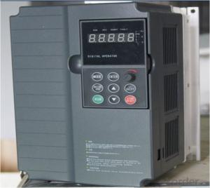
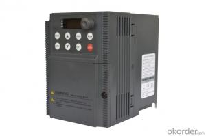
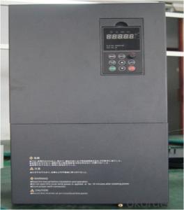
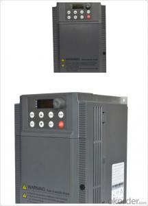
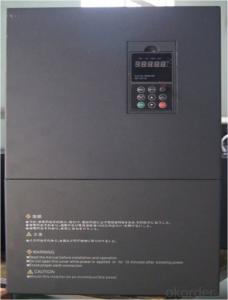
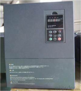
220V Single Phase Variable Frequency Drive 2.2KW
General
CNBM frequency inverter is a high-quality, multi-function,
low-noise variable frequency drive which is designed, developed and manufactured according to international standards.
It can meet different needs of industrial conditions.
The inverter applies advanced control technology of space voltage vector PWM, with functions of constant voltage control, power-off restart, dead zone compensation, automatic torque compensation, online modification parameter, high-speed impulse input, simple PLC and traverse.
Product Name:CMAX-VCG15/P18.5T3 ~ CMAX-VCG18.5/P22T3
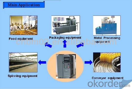
Application
Textile: coarse spinner, spinning frame, wrap-knitting machine, loom, knitting machine, silk-spinning machine, etc.
Plastic: extruder, hauling machine, decorating machine, etc.
Pharmacy: mixer, roaster, etc.
Woodworking: engraving machine, sander, veneer peeling lathe, etc.
Papermaking: single type papermaking machine, etc.
Machine tool: non-core grinding machine, optical lens grinding machine, cutting mill, etc.
Printing: cloth-washing machine, dye vat, etc.
Cement: feeder, air blower, rotary furnace, mixer, crusher, etc
Fan and pump: kinds of fans, blowers and pumps
Specification
Item | Specification | |
Input | Input voltage | 220/380V±15% |
Input frequency | 47~63Hz | |
Output | Output voltage | 0~input voltage |
Output frequency | 0~600Hz | |
Peripheral interface characteristics | Programmable digital input | 4 switch input, 1 high-speed impulse input |
Programmable analog input | AI1: 0~10V input AI2: 0~10V input or 0~20mA input, | |
Programmable open collector output | 2 Output (3.7kW and above: 1 Open collector output) | |
Relay Output | 1 Output (3.7kW and above: 2 Relay output) | |
Analog output | 2 Output, one is 0~10V, another is 0~20mA or 0~10V | |
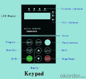
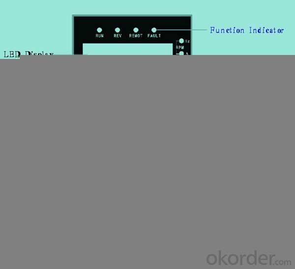
Keypad | Display:5-digit 8-section LED (Red), 2 indicators; parameter setting: 8 keys (including multi-function hot key ), 1 potentiometer | |
Technical performance characteristics | Control mode | All digital space voltage vector SVPWM algorism |
Overload capacity | G purpose: 150% rated current 60s P purpose: 120% rated current 60s | |
Speed ratio | 1: 100 | |
Carrier frequency | 1.0~10.0kHz | |
Torque compensation | Linear, multi-point, 1.3th power, 1.7th power, 2.0th power reduced torque; Compensation voltage range: automatic compensation and manual compensation 0.1~10% | |
Automatic voltage adjustment | It can automatically maintain output voltage constant when grid voltage fluctuates. | |
Automatic current adjustment | When the current is over current limit, under clocking automatically limits output current. | |
Function characteristics | Frequency setting mode | Keypad digital analog input, keypad potentiometer, impulse frequency, communication, multi-step speed and simple PLC, PID setting and so on, switch-over of setting modes. |
Simple PLC, multi-step speed control | 16-step speed control | |
Special function | Traverse control, length control, time control | |
QUICK/JOG key | User-defined multi-function hot key | |
Protection function | Over-current, Over voltage, under-voltage, over-heat, phase failure, over-load and motor over-load | |
Working condition | Installation site | Indoor, altitude of less than 1km, dust free, non-corrosive gases, no direct sunlight |
Application environment | -10°C~+40°C, 20~90%RH (no dew) | |
Vibration | Less than 0.5g | |
Storage temperature | -25°C~+65°C | |
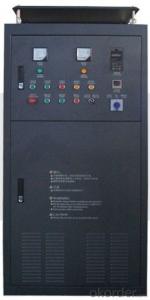
Installation type | Wall-mounted type, floor cabinet type | |
Cooling mode | Air-forced cooling | |
- Q:When the inverter is running at full 50HZ, the output voltage decreases and the output current becomes smaller. What is the reason?
- If the load of the motor is increased, the slip S is increased, the electromotive force of the motor is decreased, and the electric current of the motor will become larger. That is to say, when the motor is running in the overclocking stage, the load of the motor is light, the current will become smaller, and the current will not be smaller if the load is negative. Didn't I make myself clear?
- Q:What are the modes of operation of a frequency converter?
- If the inverter is still protected within a specified period of time, the running curve of the starting P should be changed, from the straight line to the S, U, or reverse, S, and U lines. When the motor load is large, a longer start stop time should be adopted, and the operation curve type should be set according to its load characteristics. 41 If the inverter is still running failure, try to increase the maximum current protection value, but can not cancel the protection, there should be at least 10% to 20% of the protection margin. 51, if the frequency converter operation failure or replacement, should be replaced by a larger power converter. 61 If the inverter drives the motor in the start-up process can not reach to the preset speed, there may be two cases:
- Q:What is called vector converter?
- In the electrical field is mainly used for the analysis of AC power, such as the analysis of the motor, etc., in the application of inverter in motor analysis based on the theory of frequency control, called vector control inverter, the method is not unique, but a basic mathematical model.
- Q:What does Ro1c mean on a converter?
- Relay output converter dry contact signal, RO1C is the common end and RO1A is closed, RO1B is normally open, this set of contacts is prepared to run the factory setting output signal, power on self-test is completed can run the relay output signal. It can be modified to the output point of the signal such as fault and operation in the twenty-fourth set of parameters.
- Q:What is the main function of the frequency converter on the machine tools?
- According to the working characteristics of machine tool spindle drive structure, most of the early machine adopts three-phase asynchronous motor with multi-stage gearbox, with the continuous development of technology, machine tool has been greatly improved, so as to put forward new requirements on the spindle system, and because use varies in CNC machine tools, CNC lathe, CNC drilling accounted for 42%. Boring and milling machine CNC grinding machine, punching machine accounted for 33%, accounting for 23%, accounting for 2% of the other, in order to meet the needs of the former two types of CNC machine tools a wide range of large, proposed the following requirements of the spindle drive: main drive motor power range should be 2.2KW~250KW; to have a wide range of stepless speed regulation, such as constant torque speed and 1:10 constant power speed in the range of 1:100~1000; the main transmission requirements are capable of driving the four quadrant; in order to meet the requirements of thread turning, spindle can realize synchronization control and feed.
- Q:1, the frequency converter to the motor cable should be shielded cable? 2, whether there are specifications?
- When we design the frequency converter to drag the motor load (mostly fan and water pump general machine), we should use shielded cable. We refer to the GB/T21209-2007 "inverter power supply design and performance of cage induction motors in section 9.1.4" guide "motor power cable" 9.1.4.1 "recommended configuration" in the "provisions of more than 30kW motor wiring should adopt the single core power cable or a plurality of grounding wire arranged symmetrical cable. Small power and suitable for wiring, priority is to use multi-core shielded cable." As the PE line symmetrical configuration of the 3+3 inverter dedicated cable, construction is always raised, not wiring, we later too lazy to explain, usually directly with the 3+1 type multi-core shielded cable. From the running situation, the effect is also good.
- Q:First of all, I would like to achieve the frequency converter with motor static linear acceleration, high-speed linear deceleration stop processFirst question: I say kind of situation, three paragraph speed start, 0.1hz---> high 30hz-->0.1hzSecond problem: manual speed instruction 1, speed 2, speed 3 instruction instruction I want to use PLC to control three speed motor with three reverse contact dry. I understand speed instruction 1 is switched on (2, 3 connected) transmission section set the frequency with the frequency segment set 0HZ123 AssociationThird questions: manual section, speed command, main frequency and STEP1-STEP7 stage setting frequency, I use PLC analog to the frequency main frequency setting, plus and deceleration, STEP1-7 are set 0, can achieve what I wantInitial contact frequency converter, home pointing
- Using PLC to analog converter control input frequency up to speed off from the requirements of the inverter frequency source set P-00 speed by 00 digital operation panel to analog frequency PLC given 0102 given frequency parameters can choose the set of 01 or 02 and the period of quick closing even P-17P-19 parameters affect analog control
- Q:Heating inverter commissioning steps
- The no-load connection test of the frequency converter will connect the grounding terminal of the frequency converter to the ground 1. 2 the power input terminal of the frequency converter is connected to the power supply through the leakage protection switch. 3 check the frequency converter display window factory display is normal, if not correct, should reset, or request exchange. 4 familiar with the operation key of frequency converter. The inverter has run in general (RUN) and stop (STOP), programming (PROG), P (DATAPENTER), the data confirm the increased (UP, 3), reduce (DOWN, 6) and other key definitions of different inverter operation keys are basically the same. In addition, some inverters also monitor (MONITORPDISPLAY), reset (RESET), inch movement (JOG), shift (SHIFT) and other functional keys.
- Q:It was when processing a workpiece, processing spindle stops suddenly (other are normal) a check is, I jump out of the inverter, I can click on a processing, and then processing not long after they happen, (do not open the machine spindle machining will also be the case)
- Has the frequency converter been used for a long time? The inverter power placed on the two day, and then open, put the line inside the head plug again, and then boot general can solve the problem, new don't try
- Q:What is a frequency converter?
- The frequency converter is the electric energy control device that transforms the power frequency power to another frequency by the on-off function of the power semiconductor device. The frequency converter is mainly composed of rectifier (AC DC converter), filter, inverter (DC AC converter), brake unit, drive unit, detection unit, micro processing unit and so on.
1. Manufacturer Overview |
|
|---|---|
| Location | |
| Year Established | |
| Annual Output Value | |
| Main Markets | |
| Company Certifications | |
2. Manufacturer Certificates |
|
|---|---|
| a) Certification Name | |
| Range | |
| Reference | |
| Validity Period | |
3. Manufacturer Capability |
|
|---|---|
| a)Trade Capacity | |
| Nearest Port | |
| Export Percentage | |
| No.of Employees in Trade Department | |
| Language Spoken: | |
| b)Factory Information | |
| Factory Size: | |
| No. of Production Lines | |
| Contract Manufacturing | |
| Product Price Range | |
Send your message to us
Frequency Inverter VFD
- Ref Price:
-
- Loading Port:
- China Main Port
- Payment Terms:
- TT OR LC
- Min Order Qty:
- -
- Supply Capability:
- -
OKorder Service Pledge
OKorder Financial Service
Similar products
New products

Hot products
Hot Searches
Related keywords

